Multivane segment mounting arrangement for a gas turbine

a gas turbine and multi-vane technology, applied in the field of gas turbines, can solve the problems of unsatisfactory thermal stress and exacerbate the problem of the vane arrangemen

Inactive Publication Date: 2008-11-13
SIEMENS ENERGY INC
View PDF22 Cites 73 Cited by
  • Summary
  • Abstract
  • Description
  • Claims
  • Application Information

AI Technical Summary

Problems solved by technology

A problem arises however, in that the ceramic vanes have a substantially different coefficient of thermal expansion than the metal support structure such that when heated and cooled, the vanes and support structure

Method used


Image

  • Multivane segment mounting arrangement for a gas turbine
  • Multivane segment mounting arrangement for a gas turbine
  • Multivane segment mounting arrangement for a gas turbine

Examples


Embodiment Construction

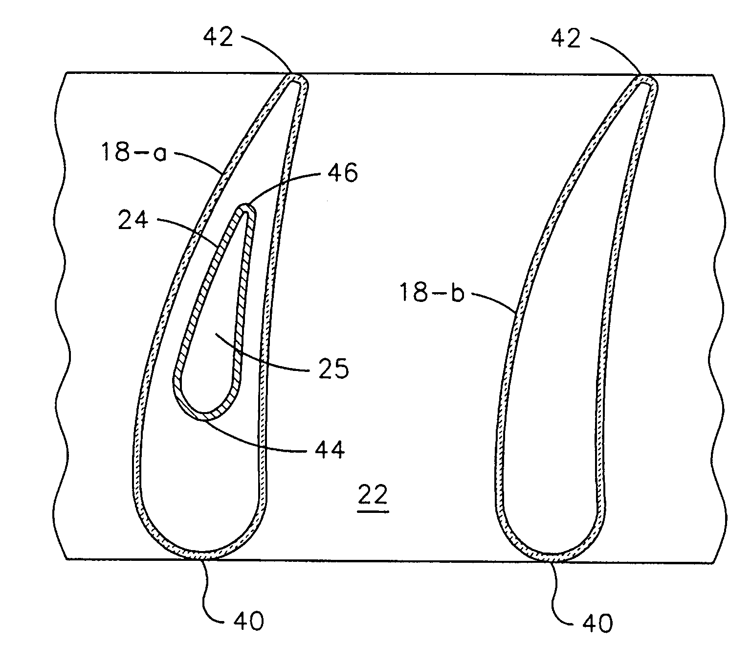
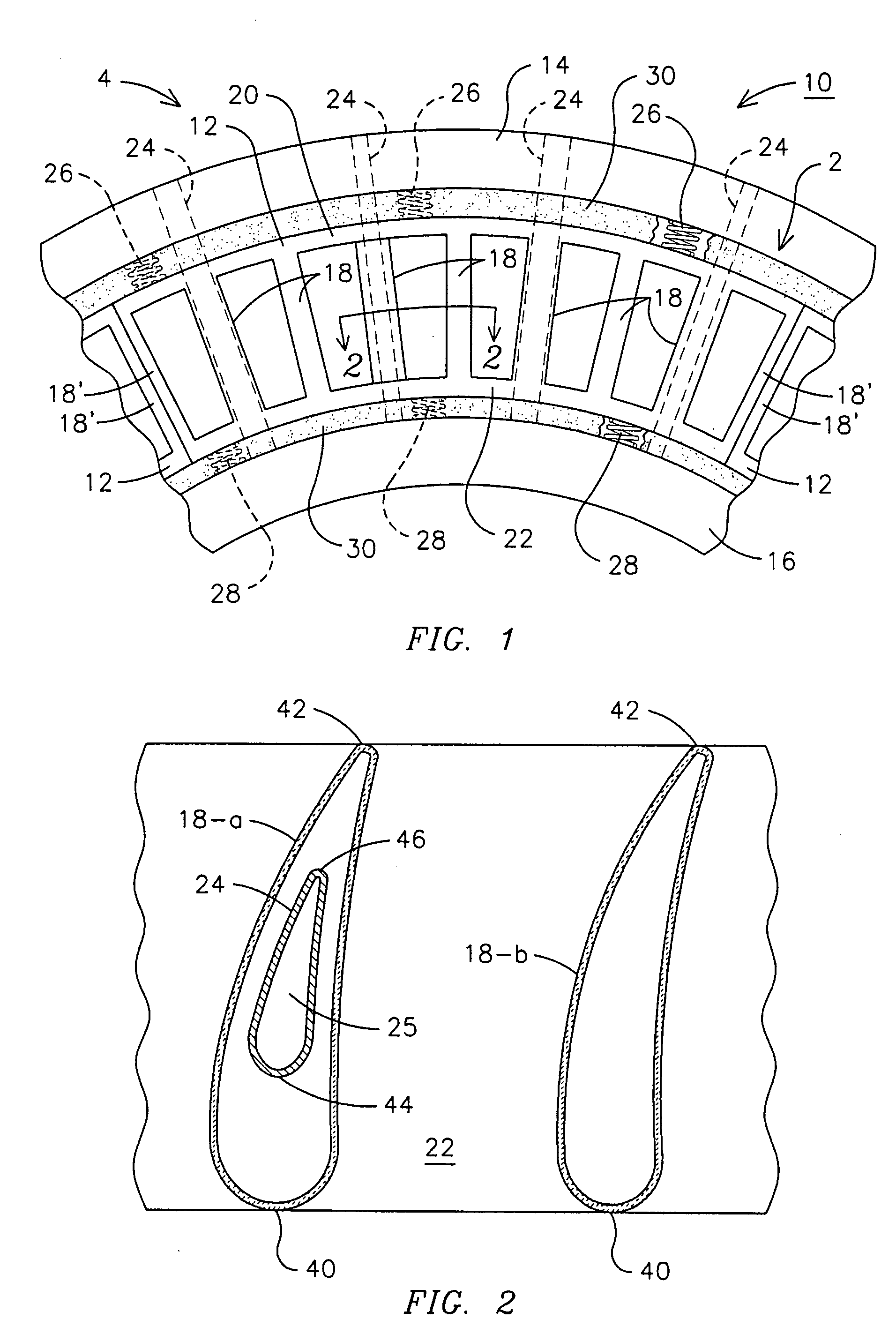
[0009]FIG. 1 is a partial view of a vane stage 2 of a gas turbine engine 4 as viewed along an axis of the turbine rotor (not shown) and illustrating a multivane segment mounting arrangement 10. The multivane segment mounting arrangement 10 includes a plurality of multivane segments 12 positioned between an outer ring 14 and an inner ring 16, which in turn are connected directly or indirectly to the turbine casing structure (not illustrated). The outer ring 14 and inner ring 16 may be constructed of metal alloy materials as are known in the art. The multivane segment 12 is formed of a specialized material which has a different coefficient of thermal expansion than the outer and inner rings 14 and 16. In one embodiment, the multivane segment 12 is formed of a ceramic matrix composite (CMC) material. A wide range of CMCs have been developed that combine a matrix material with a reinforcing phase of a different composition. Such CMCs combine high temperature strength with improved fract...


PUM


Abstract

A mounting arrangement (10) for a multivane segment (12) of ceramic matrix composite (CMC) composition positioned between outer and inner metallic rings (14, 16). Selected ones of the vanes (18a) of the multivane segment surround internal struts (24) joining the outer and inner rings. Spring members (26, 28) accommodate differential thermal growth between the multivane segment and the outer and inner rings, and a compliant material (30) seals against gas leakage around the segments.

Description

FIELD OF THE INVENTION[0001]The invention in general relates generally to gas turbines, and particularly to a novel vane arrangement for a gas turbine.BACKGROUND OF THE INVENTION[0002]The turbine section of a gas turbine is comprised of a plurality of stages, each including a set of stationary vanes and a set of rotating blades. Hot gas is directed through the vanes to impinge upon the blades causing rotation of turbine rotor assembly to which they are connected. The power imparted to the rotor assembly may be used to rotate other machinery such as an electric generator, by way of example.[0003]Advanced turbine systems have been developed which use vanes made of ceramic matrix composite material which can withstand much higher temperatures than conventional metal vanes. These high temperature vanes are connected to a metallic support arrangement. A problem arises however, in that the ceramic vanes have a substantially different coefficient of thermal expansion than the metal support...

Claims


Application Information

Patent Timeline
IPC IPC(8): F04D29/44
CPCF04D29/023F04D29/542F04D29/644F01D9/042F01D25/246F05D2230/642F05D2300/6033
Inventor MORRISON, JAY A.
Owner SIEMENS ENERGY INC
Why Eureka
Try Eureka