Polymeric Fluid Transfer and Printing Devices

a technology applied in the field of fluid transfer and printing device, can solve the problems of inability to manufacture the utility of pins, high cost of pins, and inability to machine microspotting pins individually

Inactive Publication Date: 2008-11-13
HAUSHALTER ROBERT C
View PDF67 Cites 27 Cited by
  • Summary
  • Abstract
  • Description
  • Claims
  • Application Information

AI Technical Summary

Problems solved by technology

Unfortunately, the metal microspotting pins are individually machined at costs up to $400 each.
The high cost of the pins prohibit many laboratories from using microspotting pin technology.
Mor

Method used


Image

  • Polymeric Fluid Transfer and Printing Devices
  • Polymeric Fluid Transfer and Printing Devices
  • Polymeric Fluid Transfer and Printing Devices

Examples


Embodiment Construction

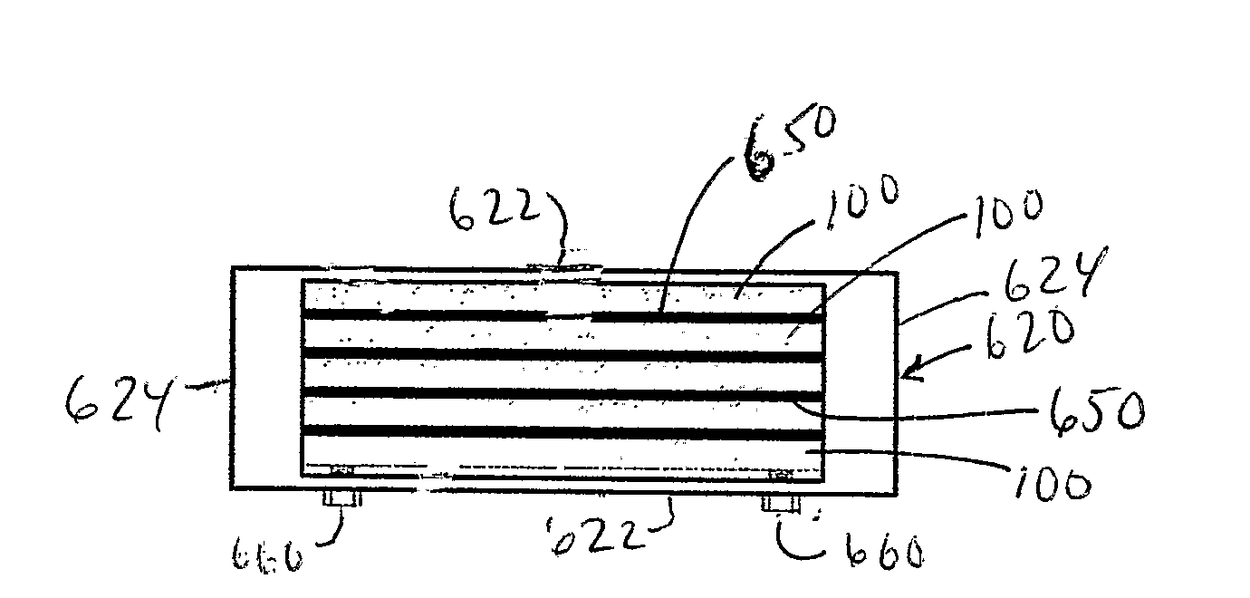
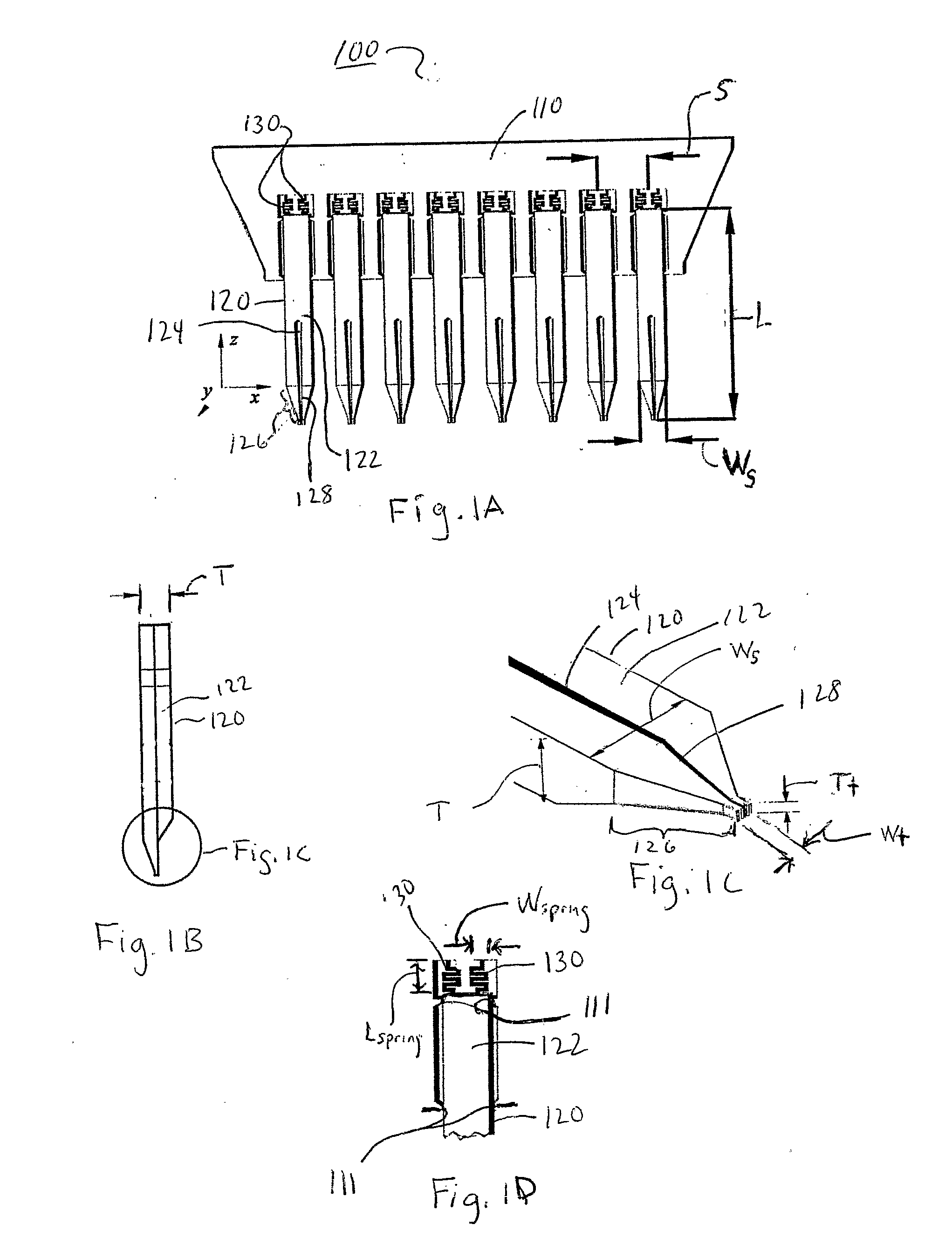
[0032]FIGS. 1A-1D collectively show an embodiment of a unitarily formed polymeric printhead 100 comprising a head member 110 and a linear array of polymeric pins 120 each of which is connected to the head member 110 by flexible springs 130. Each of the pins 120 may comprise a shaft 122 and a printing tip section 123. The printing tip section 123 may comprise a tapering, channel-like fluid or sample reservoir 124, a dispensing or print tip 126 and a slot 128 extending through the print tip 126 and communicating with the reservoir 124. The head member 110 includes collimating surface portions 111 (FIG. 1D) immediately adjacent the pins 120, to collimate the pins 120 thereby preventing them from tilting during printing on a substrate. The slot 128 enables a fluid (e.g., a sample in solution) to be drawn into and stored in the reservoir 124, transferred, and then dispensed at the print tip 126. It is contemplated that in other embodiments, the polymeric pins, may comprise holes, slots o...


PUM

PropertyMeasurementUnit
Volumeaaaaaaaaaa
Volumeaaaaaaaaaa
Areaaaaaaaaaaa

Abstract

A method and apparatus for making a polymeric printhead having one or more pins for fluid transfer and printing, including the steps of forming a positive mold of the printhead using a bulk micromachining process, forming a negative mold of the printhead from the positive mold using an electroforming process, and forming the printhead from a polymeric material in the negative mold, the polymeric printhead being operative for fluid transfer and/or printing. Also, printheads and pins, holders and dispensing trays microfabricated from a polymeric materials for fluid transfer and printing.

Description

RELATED APPLICATIONS[0001]This application claims the benefit of U.S. Provisional Application No. 60 / 661,833, filed on Mar. 1, 2005, the entire disclosure of which is incorporated herein by reference.[0002]U.S. Patent Publication 20030166263 A1, entitled MICROFABRICATED SPOTTING APPARATUS FOR PRODUCING LOW COST MICROARRAYS.FIELD OF THE INVENTION[0003]This invention relates to fluid transfer and printing devices. More particularly, the invention relates to improved fluid transfer and printing devices and methods and apparatus for producing same.BACKGROUND OF THE INVENTION[0004]Microarray technology is emerging as one of the principal and fundamental investigational tools for a very wide variety of biological problems. Although the preparation of DNA microarrays for use in many types of analysis is one of the main applications today, it is clear that the basic concept of easily obtaining huge amounts of data from a rapid and relatively simple-to-use platform is set to penetrate most a...

Claims


Application Information

Patent Timeline
IPC IPC(8): C25D1/00B01L3/00B01L9/00
CPCB01J19/0046B01J2219/00317B01J2219/00385B01J2219/00387B01J2219/00527B01J2219/00585B01J2219/00596B01J2219/00605B01J2219/00659B01J2219/00722B01J2219/00725B01L3/0248B01L3/0255B01L9/543B01L2200/12G01N35/1065G01N2035/1037
Inventor HAUSHALTER, ROBERT C.
Owner HAUSHALTER ROBERT C
Why Eureka
Try Eureka