
Multi-Purpose Optical Mouse

a multi-purpose, optical mouse technology, applied in the field of pointing devices, can solve the problems of difficulty in use, inefficient housing of different functional components, etc., and achieve the effect of simple operation

Inactive Publication Date: 2008-11-20
ACT-ON
View PDF3 Cites 35 Cited by
  • Summary
  • Abstract
  • Description
  • Claims
  • Application Information

AI Technical Summary

Problems solved by technology

The device provides portability and enables multiple functions, but the different functional components are housed in a very inefficient manner.
As a result, ease of use is a problem with this device.

Method used


Image

  • Multi-Purpose Optical Mouse
  • Multi-Purpose Optical Mouse
  • Multi-Purpose Optical Mouse

Examples


Embodiment Construction

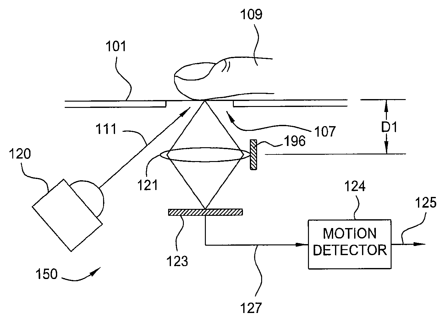
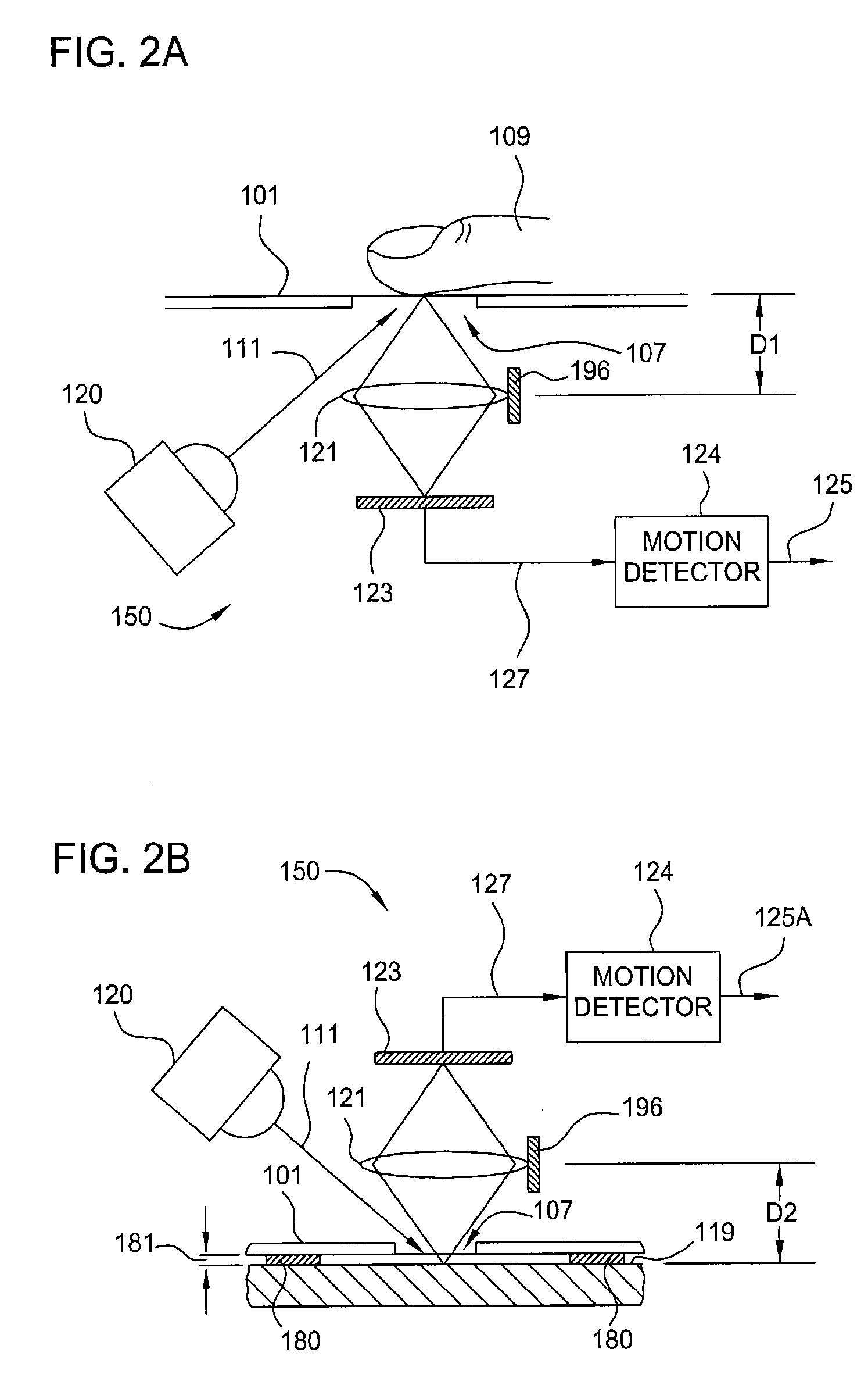
[0023]Embodiments of the invention contemplate a pointing device for a computing device having a rotatable optics housing, which may provide cursor control in one of two modes: a finger navigation mode and a desktop navigation mode. In the finger navigation mode, the rotatable optics housing is in a first position and moving a finger across a transparent plate in the optics housing controls the cursor movement. In the desktop navigation mode, the rotatable optics housing is in a second position and moving the entire optical mouse in a conventional manner across a fixed surface controls cursor movement.

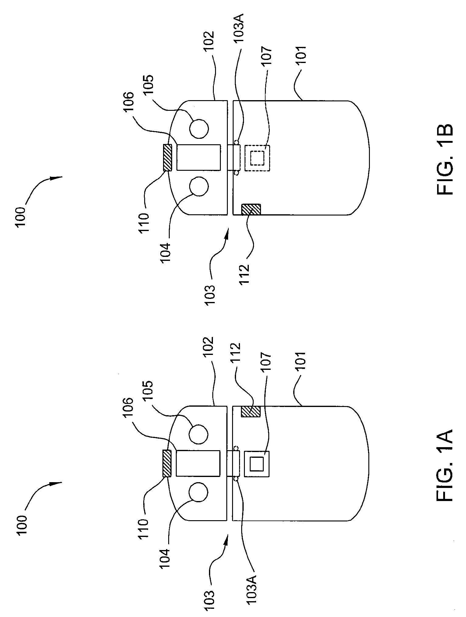
[0024]FIGS. 1A and 1B illustrate schematic plan views of an optical mouse 100 that is employed as a pointing device according to embodiments of the invention. Optical mouse 100 is relatively small in size to facilitate use as a hand-held computer input device, and includes an optical housing 101 coupled to a control button assembly 102 by a rotary coupling 103. Rotary coupling 103 incl...


PUM


Abstract

An optical pointing device has a rotatable optics housing and provides cursor control in one of two modes: a finger navigation mode and a desktop navigation mode. In the finger navigation mode, the rotatable optics housing is in a first position and moving a finger across a transparent plate in the optics housing controls the cursor movement. In the desktop navigation mode, the rotatable optics housing is in a second position and moving the entire optical mouse in a conventional manner across a fixed surface controls cursor movement. The optical pointing device may further include a touchpad scroll input device and a laser pointing device.

Description

BACKGROUND OF THE INVENTION[0001]1. Field of the Invention[0002]Embodiments of the present invention relate generally to pointing devices for computing devices, and in particular, to a multi-purpose optical mouse.[0003]2. Description of the Related Art[0004]Computers are increasingly being used for graphical presentations that are displayed to a group of people. Many presentations, such as slide shows, require relatively simple control of the computer, such as commands for advancing or moving back through slides. For these, simple input devices with user-actuated buttons for advancing or moving back through the presentation have been developed. Some presentations require a more sophisticated control of the computer. For these, it is necessary for the presenter to remain in close proximity of the computer to operate a conventional pointing device, such as a mouse, trackball, touchpad, etc.[0005]U.S. Pat. No. 7,161,578 discloses a pointing device that is particularly suitable for use ...

Claims


Application Information

Patent Timeline
Patent Type & Authority Applications(United States)
IPC IPC(8): G06F3/033
CPCG06F3/0317G06F3/03549G06F3/042
Inventor SHIM, THEODORE I.
Owner ACT-ON
Learn More