System and Method for Illumination and Fixation with Ophthalmic Diagnostic Instruments

Active Publication Date: 2008-11-20
AMO DEVMENT
View PDF37 Cites 139 Cited by
  • Summary
  • Abstract
  • Description
  • Claims
  • Application Information

AI Technical Summary

Benefits of technology

[0015]The present invention generally provides improved devices, systems, and methods for measuring, diagnosing, and/or treating refractive error, aberrations and other vision defects. The devices, systems and methods of embodiments of the present invention are particularly well-suited for measuring refractive optical aberrations of the eye and can be well-suited for developing general or customized prescriptions for treatment of vision defects. In some embodiments, the devices, systems and methods of the present invention will make use of a target on a display that moves transverse to an optical path from the display to the eye, so as to relax accommodation of the lens of the eye. The patient may be fogged while the target moves transverse to the optical path on the display, and the target may become smaller such that the patient perceives the target to be moving away from the patient. Many kinds of transverse target motion can be employed including translation and rotation of the target shown on the display. In some embodiments, a pupil camera measures eye position that can be correlated with the

Problems solved by technology

In some instances, the optical characteristics of the eye may change and can make accurate measurements of the eye difficult.
If a patient's eye accommodates for near vision during measurements of the eye's refraction, the patient may receive an improper amount of optical correction that can make the treatment less than ideal.
For example with nearsightedness, overcorrection of the patient can result from patient accommodation for a near target during the refractive measurement of the eye.
This overcorrection can make the patient far sighted, or hyperopic, once the accommodation relaxes.
Consequently, the patient may not have good near vision as the patient may be unable to overcome the overcorrection to see objects that are near.
With the diagnosis and treatment of hyperopia, hyperopic patients often accommodate during both near and far vision so as to compensate for their hyperopia, such that these patients may have trouble relaxing their accommodation during measurements, even when viewing targets at a distance.
Consequently, residual amounts of hyperopia may not be detected.
Incomplete assessment of hyperopia ca

Method used


Image

  • System and Method for Illumination and Fixation with Ophthalmic Diagnostic Instruments
  • System and Method for Illumination and Fixation with Ophthalmic Diagnostic Instruments
  • System and Method for Illumination and Fixation with Ophthalmic Diagnostic Instruments

Examples


Example

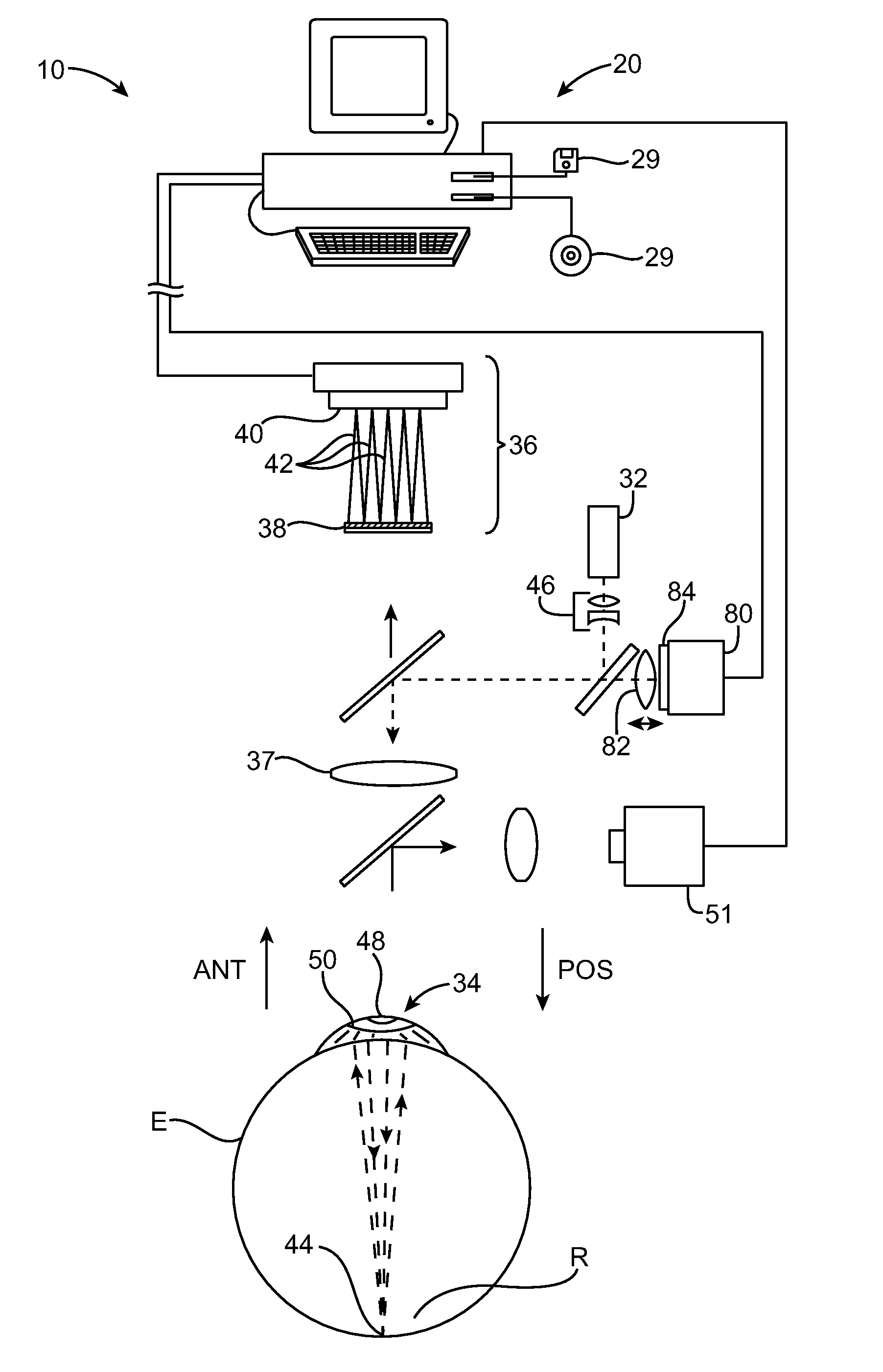
[0039]The present invention generally provides devices, systems, and methods for diagnosing, measuring and / or treating one or both eyes of a patient. The invention allows measurement of the eye with the measurement system positioned near the eye while the eye is relaxed so as to relax an accommodative response of the eye. The invention also allows accommodation of an eye to be objectively determined, optionally based on measurements of the ocular optics. Embodiments of the present invention also allow candidate refractive eye prescriptions to be evaluated objectively and / or subjectively, often without having to fabricate one or more individual test lenses, even when customized prescriptive shapes are to be implemented and evaluated at a plurality of viewing conditions (such as different viewing distances, lighting conditions, and the like). Hence these embodiments of the present invention will find applications for measuring and treating a variety of defects of the eye, including pr...


PUM


Abstract

An eye measurement system may include a target that moves transverse to an optical path from the target to eye, so as to relax accommodation of the lens of the eye. The target may move transverse to the optical path on a display. The patient may be fogged while the target moves transverse to the optical path, and the target may become smaller such that the patient perceives the target to be moving away from the patient. A pupil camera may measure eye position that can be correlated with the position of the target on the display to determine that the patient has maintained fixation on the moving target. A visible measurement light beam may be pulsed subsequent to and/or during motion of the target that relaxes accommodation of the eye so as to avoid visual interference of the measurement light beam with the target on the display.

Description

CROSS-REFERENCES TO RELATED APPLICATIONS[0001]NOT APPLICABLESTATEMENT AS TO RIGHTS TO INVENTIONS MADE UNDER FEDERALLY SPONSORED RESEARCH OR DEVELOPMENT[0002]NOT APPLICABLEREFERENCE TO A “SEQUENCE LISTING,” A TABLE, OR A COMPUTER PROGRAM LISTING APPENDIX SUBMITTED ON A COMPACT DISK[0003]NOT APPLICABLEBACKGROUND OF THE INVENTION[0004]This invention relates to diagnosis and / or measurement of the optical properties of the eye. Embodiments of the present invention provide systems, devices, and methods to measure, diagnose and treat optical properties of an eye. Although specific mention is made to wavefront measurements of the eye, embodiments of the present invention can be used with many instruments that measure and / or treat optical properties of the eye, for example auto refractors and laser eye surgery systems.[0005]The eye has many transparent tissue structures that are shaped to form images on the retina. Many of these tissue structures, such as the cornea and crystalline lens each...

Claims


Application Information

Patent Timeline
IPC IPC(8): A61B3/103
CPCA61B3/103A61B3/0091
Inventor YEE, KINGMANSOMANI, SEEMA
Owner AMO DEVMENT
Why Eureka
Try Eureka