Terminal, base station, transmission method, and reception method
- Summary
- Abstract
- Description
- Claims
- Application Information
AI Technical Summary
Benefits of technology
Problems solved by technology
Method used
Image
Examples
embodiment 1
Overview of Communication System
[0047]A communication system according to Embodiment 1 of the present invention includes base station 100 and terminals 200. Base station 100 is an LTE-A compliant base station and terminals 200 are LTE-A compliant terminals.
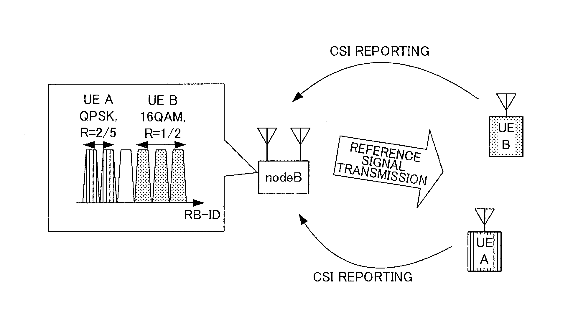
[0048]FIG. 4 is a main configuration diagram of base station 100 according to Embodiment 1 of the present invention. In base station 100, configuration section 101 configures resources (interference estimation resources) from a reference signal resource group (CSI-RS configuration), transmission processing section 104 transmits control information including the above-described resources to terminal 200, and reception processing section 108 receives channel information (CSI) generated using signals transmitted from TPs other than a specific TP and a reference signal (CSI-RS) transmitted from the specific TP using resources identified from the control information in terminal 200.
[0049]FIG. 5 is a main configuration diagram of termin...
embodiment 2
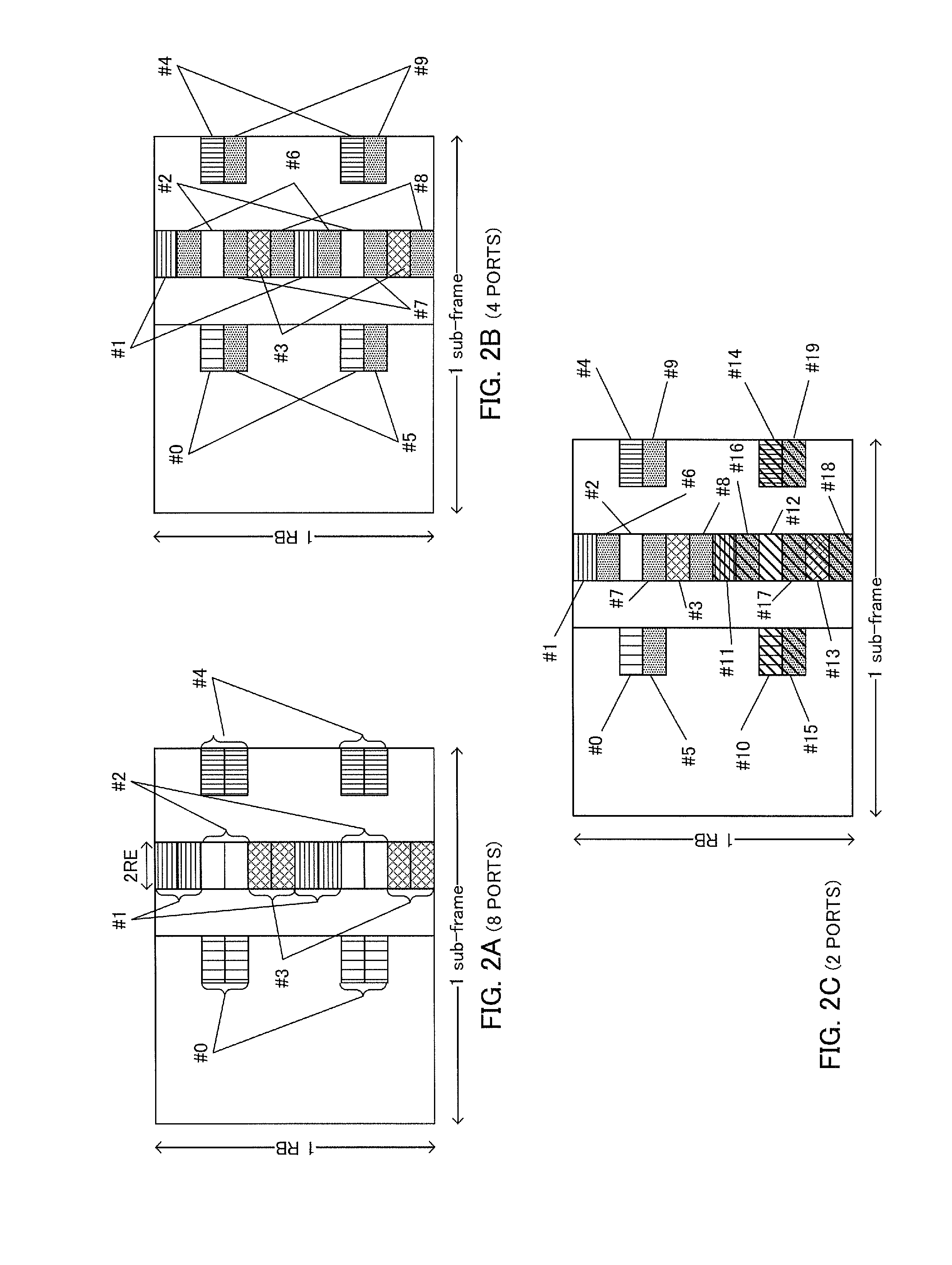
[0092]A case has been described in Embodiment 1 where parameters indicating non-transmission signal resources of a TP (non-transmission CSI-RS configuration number list) are used as interference estimation resources of the TP without modification.
[0093]However, the terminal has not acquired information relating to CSI-RS of TPs not coordinating with the TP to which the terminal is connected. Thus, the terminal cannot identify whether or not the non-coordinating TPs are transmitting CSI-RSs using the indicated non-transmission signal resources (interference estimation resources). That is, the terminal cannot determine whether non-transmission signal resources configured in the TP to which the terminal is connected and CSI-RS resources configured in the non-coordinating TPs overlap (collide) with each other.
[0094]Here, in interference estimation, the terminal is intended to observe signal components arriving from TPs other than a target TP (CSI measurement target) and estimate the obs...
embodiment 3
[0132]A case has been described in Embodiment 2 where CSI-RS config(i) corresponding to some resources making up interference estimation resources is indicated from a base station to a terminal. In contrast, the present embodiment will describe a case where interference estimation resources are indicated from a base station to a terminal in bitmap notation.
[0133]Since the base station and terminal according to the present embodiment have basic configurations common to those of base station 100 and terminal 200 according to Embodiment 1, they will be described with reference to FIGS. 6 and 7.
[0134]In base station 100, configuration section 101 generates interference estimation resource information for CSI reporting target terminal 200 just as in Embodiment 2. However, unlike Embodiment 2, configuration section 101 generates an interference estimation CSI-RS configuration number list in bitmap notation as interference estimation resource information as in the parameters of non-transmi...
PUM
 Abstract
Description
Claims
Application Information
 - R&D
- Intellectual Property
- Life Sciences
- Materials
- Tech Scout
- Unparalleled Data Quality
- Higher Quality Content
- 60% Fewer Hallucinations
Browse by: Latest US Patents, China's latest patents, Technical Efficacy Thesaurus, Application Domain, Technology Topic, Popular Technical Reports.
© 2025 PatSnap. All rights reserved.Legal|Privacy policy|Modern Slavery Act Transparency Statement|Sitemap|About US| Contact US: help@patsnap.com


