

Apparatus for the correction of temperature drift for pressure sensor, pressure control apparatus and pressure-type flow rate control apparatus
- Summary
- Abstract
- Description
- Claims
- Application Information
AI Technical Summary
Benefits of technology
Problems solved by technology
Method used
Image

Examples
Embodiment Construction
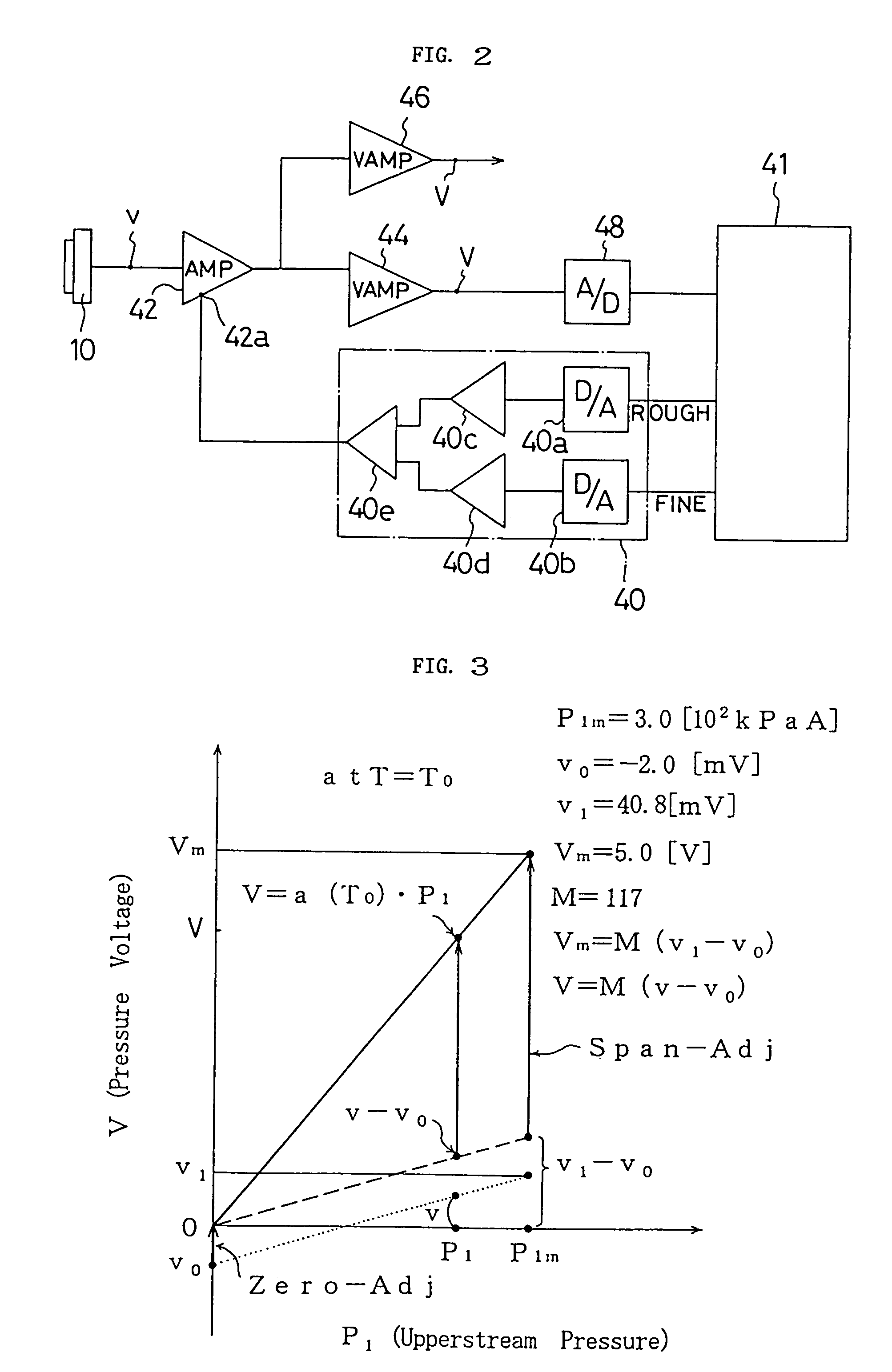
[0100]By analysing the zero-point output drift and span output drift of a pressure sensor caused by a temperature change, the inventors have succeeded in developing a method of correcting the temperature drift, not only for the pressure sensor, but also for a pressure control apparatus, and a pressure-type flow rate control apparatus in which the pressure sensor is used.
[0101]Embodiments of the apparatus for correcting temperature drift for a pressure-type flow rate control apparatus according to the present invention will be described below with reference to the drawings.
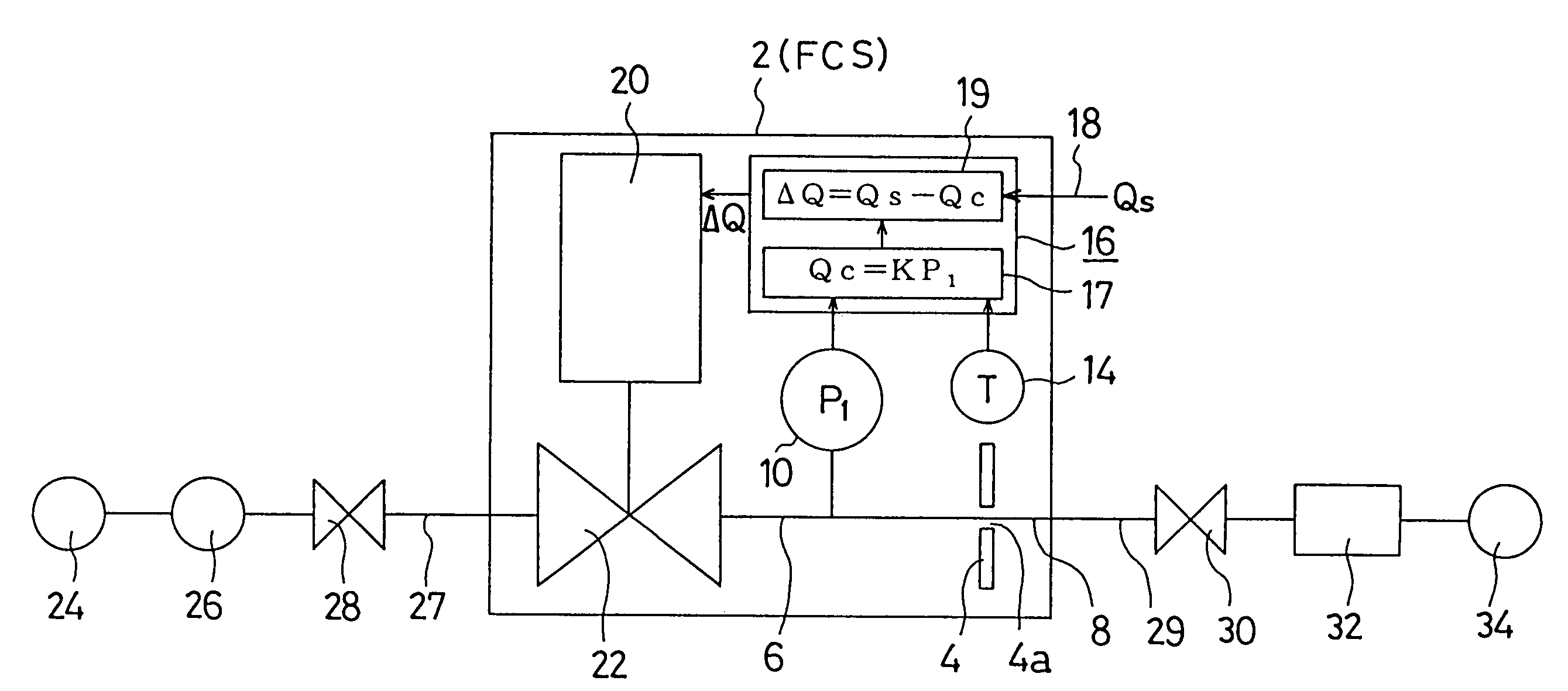
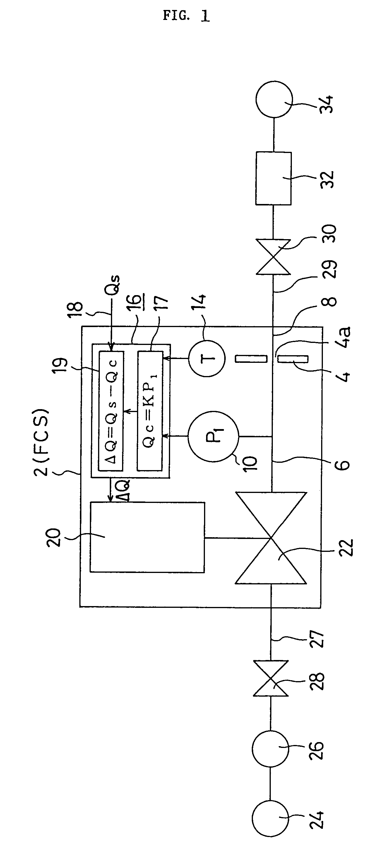
[0102]FIG. 1 is a schematic diagram of flow rate control according to the present invention using a pressure-type flow rate control apparatus which operates under critical conditions. In said pressure-type flow rate control apparatus 2, it is a prerequisite that a fluid to be supplied is under critical conditions, i.e. that the velocity of the fluid flowing out of an orifice 4 is at sonic velocity. The flow rate ca...
PUM
 Abstract
Description
Claims
Application Information