Motor controller system for large dynamic range of motor operation

Inactive Publication Date: 2006-07-25
AERONAUTICS & SPACE ADMINISTATION UNITED STATES OF AMERICA AS REPRESENTED BY THE ADMINISTATOR OF THE NAT +1
View PDF35 Cites 12 Cited by
  • Summary
  • Abstract
  • Description
  • Claims
  • Application Information

AI Technical Summary

Benefits of technology

[0006]Accordingly, it is an object of the present invention to provide a control system

Problems solved by technology

Unfortunately, there are numerous problems with these two-motor systems.
For example, stepper motors inherently waste power, are not normally designed to operate at high speeds, and have resonant frequencies of operation that can induce vibrations in the system to which the

Method used


Image

  • Motor controller system for large dynamic range of motor operation
  • Motor controller system for large dynamic range of motor operation

Examples


Example

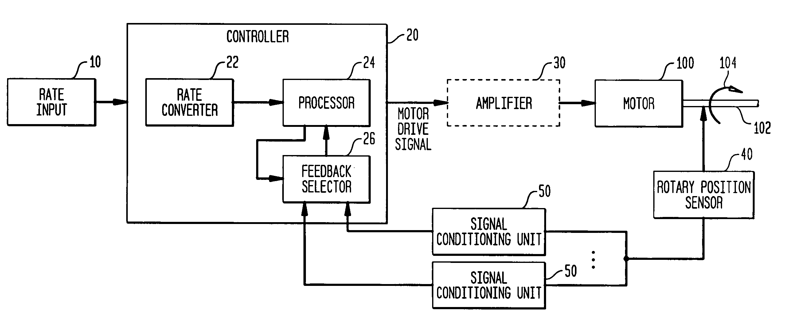
[0012]Referring now to the drawings, and more particularly to FIG. 1, a motor controller system according to the present invention is shown coupled to a motor 100. By way of illustrative example, motor 100 is a DC brushless servo motor although other motors such as a DC brush motor or AC induction motor could also be controlled by the present invention. As is known in the art, motor 100 has an output shaft 102 that rotates (as indicated by arrow 104) at a rate dictated by a drive signal supplied to motor 100. Although not shown, a device or system to be driven by output shaft 102 would be coupled thereto as is well known in the art. The present invention controls the motor's drive signal to thereby control the rotation rate of output shaft 102 from very slow rates of rotation (e.g., much less than one revolution per minute or RPM) to very fast rates of rotation (e.g., on the order of several thousand RPMs or more).

[0013]A selected rate of rotation (e.g., in RPM) for output shaft 102...


PUM


Abstract

A motor controller system uses a rotary sensor with a plurality of signal conditioning units, coupled to the rotary sensor. Each of these units, which is associated with a particular range of motor output shaft rotation rates, generate a feedback signal indicative of the position of the motor's output shaft. A controller (i) converts a selected motor output shaft rotation rate to a corresponding incremental amount of rotational movement for a selected fixed time period, (ii) selects, at periodic completions of the selected fixed time period, the feedback signal from one of the signal conditioning units for which the particular range of motor output shaft rotation rates associated therewith encompasses the selected motor output shaft rotation rate, and (iii) generates a motor drive signal based on a difference between the incremental amount of rotational movement and the feedback signal from the selected one of the signal conditioning units.

Description

ORIGIN OF THE INVENTION[0001]The invention was made in performance of work under a NASA contract and by employees of the United States Government and is subject to the provisions of Public Law 96-517 (35 U.S.C. §202) and may be manufactured and used by or for the Government of the United States of America for governmental purposes without the payment of any royalties thereon or therefor. In accordance with 35 U.S.C. §202, the Contractor has elected not to retain title.BACKGROUND OF THE INVENTION[0002]1. Field of the Invention[0003]This invention relates to motor controllers. More specifically, the invention is a motor controller system that provides a large dynamic range of motor operation for a single motor.[0004]2. Description of the Related Art[0005]Many mechanical drive system applications (e.g., robotics, materials processing furnaces, medical scanning devices, telescope drives, solar array drives, etc.) require that motor rates (e.g., revolutions per minute) be controlled for ...

Claims


Application Information

Patent Timeline
IPC IPC(8): G05B5/01
CPCH02P6/16
Inventor HOWARD, DAVID E.ALHORN, DEAN C.SMITH, DENNIS A.DUTTON, KENNETH R.PAULSON, MITCHELL SCOTT
Owner AERONAUTICS & SPACE ADMINISTATION UNITED STATES OF AMERICA AS REPRESENTED BY THE ADMINISTATOR OF THE NAT
Why Eureka
Try Eureka