Delay control method

Inactive Publication Date: 2006-04-18
NOKIA TECHNOLOGLES OY
View PDF8 Cites 13 Cited by
  • Summary
  • Abstract
  • Description
  • Claims
  • Application Information

AI Technical Summary

Benefits of technology

[0014]The object of the invention is to realize a delay control method for allowing more accurate control of delays than in the prior art systems. A furt

Problems solved by technology

New developments, such as macro diversity combining, increase the complexity of a network.
In such a configuration, problems are caused by the fact that each downlink packet has to be sent from each BS towards the MS at roughly the same time or within a small time window, while the delay from the RNC to base stations varies.
A further problem in downlink direction is, how to keep the difference between the sending time of packets from RNC and transmission time of the packets by the base stations in minimum, while still fulfilling the edge condition, that each BS receives the data before it has to be transmitted.
In the

Method used


Image

  • Delay control method
  • Delay control method
  • Delay control method

Examples


Example

[0023]Same reference numerals are used for similar entities in the figures.

DETAILED DESCRIPTION

Adjustment of Delays in the Downlink Direction

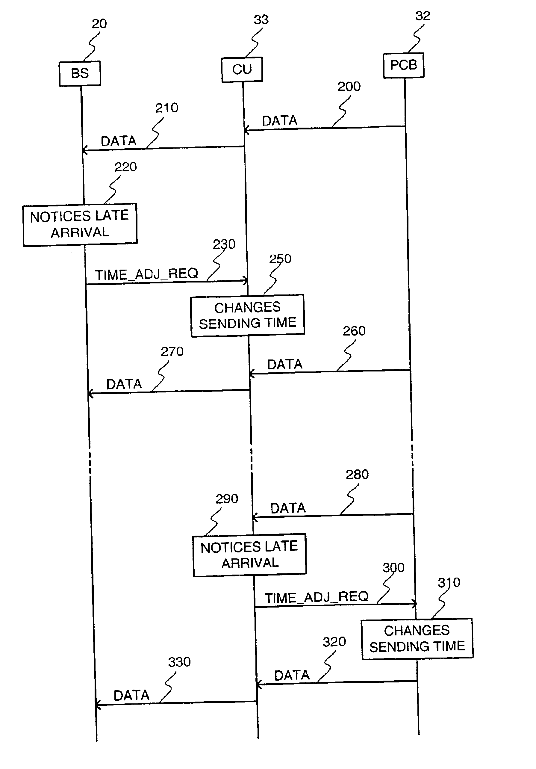
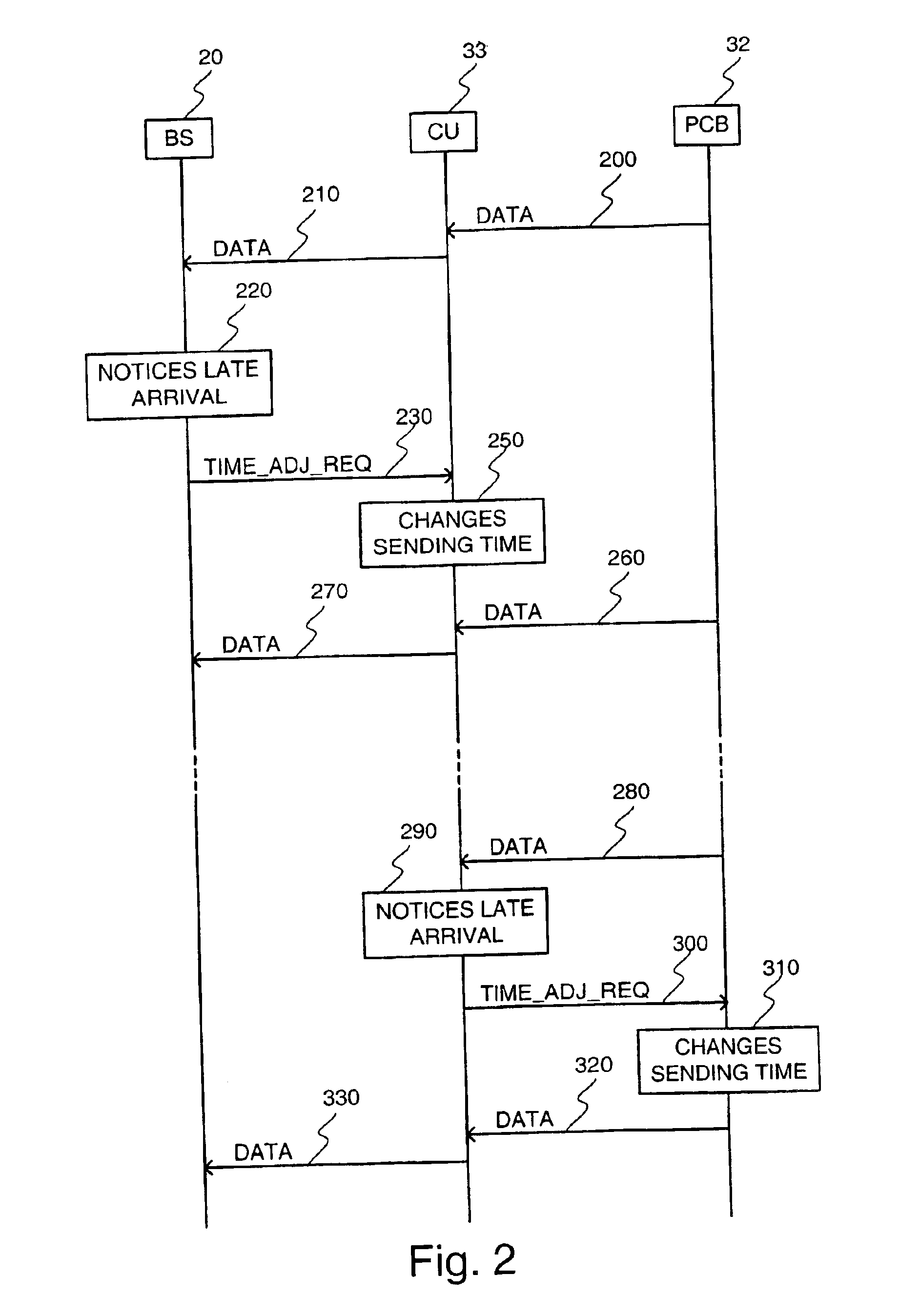
[0024]In the downlink direction, the delays are adjusted as follows according to an advantageous embodiment of the invention. If an entity, herein called the receiving entity, receives packets too late for one or more bearers, or if packets are received too early, before a certain predefined point in time, the receiving entity informs the entity preceding it in the downlink direction in the transmission path about the inaccurate timing. As a response, the preceding entity adjusts the transmission time of the packets to bring the arrival time of the packets to the receiving entity closer to the desired arrival time. In case the preceding entity cannot send the packets earlier due to the arrival time of packets to the preceding entity, the preceding entity may also inform the entity before it in the downlink direction of the transmission path, th...


PUM


Abstract

The invention is directed to a method for controlling delays in a cellular telecommunications network. The delay control method according to the invention is based on a hierarchical structure of delay controlling entities, which preferably communicate only with entities directly above or below them in the hierarchy. In the downlink direction, an entity receiving data, such as a base station or a splitting unit, sends a timing report to the entity sending the data if the data is received too early or too late, whereafter the sending entity may adjust the sending time of data. The same reporting and adjusting process may be repeated through all levels of the control hierarchy, resulting in a collective control of delays from the top of the hierarchy, for example from a RNC, to the bottom, for example to a base station. In the uplink direction, a higher level entity receiving data from a lower level entity may command the lower level entity to adjust the sending time, if the data is received too early or too late. When the same action is repeated in all levels of the hierarchy, a collective control of delays is achieved for the link between the lowest level, e.g. the base station, and the highest level, e.g. a RNC.

Description

PRIORITY CLAIM[0001]This is a U.S. national stage of application No. PCT / FI99 / 00269, filed on March 31, 1999. Priority is claimed on that application and on the following application:[0002]Country: Finland, Application No.: 980735, Filed: Mar. 31, 1998.TECHNICAL FIELD OF THE INVENTION[0003]The invention is directed to a method for controlling delays in a cellular telecommunications network.BACKGROUND OF THE INVENTION[0004]Modern cellular telecommunication systems comprise complicated structures of network elements. New developments, such as macro diversity combining, increase the complexity of a network. Macro diversity combining (MDC) refers to a situation, where terminal unit of a cellular telecommunication system has simultaneous connections to at least two base stations, in which case any given data unit can be routed to the terminal unit or from the terminal unit via at least two routes. The set of such base stations is called the active set. Macro diversity combining can be ut...

Claims


Application Information

Patent Timeline
IPC IPC(8): H04Q7/20H04B7/02H04W36/18
CPCH04B7/022H04W36/18
Inventor AHMAVAARA, KALLEKEKKI, SAMI
Owner NOKIA TECHNOLOGLES OY
Why Eureka
Try Eureka