
Glass preform manufacturing method

Active Publication Date: 2012-03-15
THE FUJIKURA CABLE WORKS LTD
View PDF2 Cites 13 Cited by
  • Summary
  • Abstract
  • Description
  • Claims
  • Application Information

AI Technical Summary

Benefits of technology

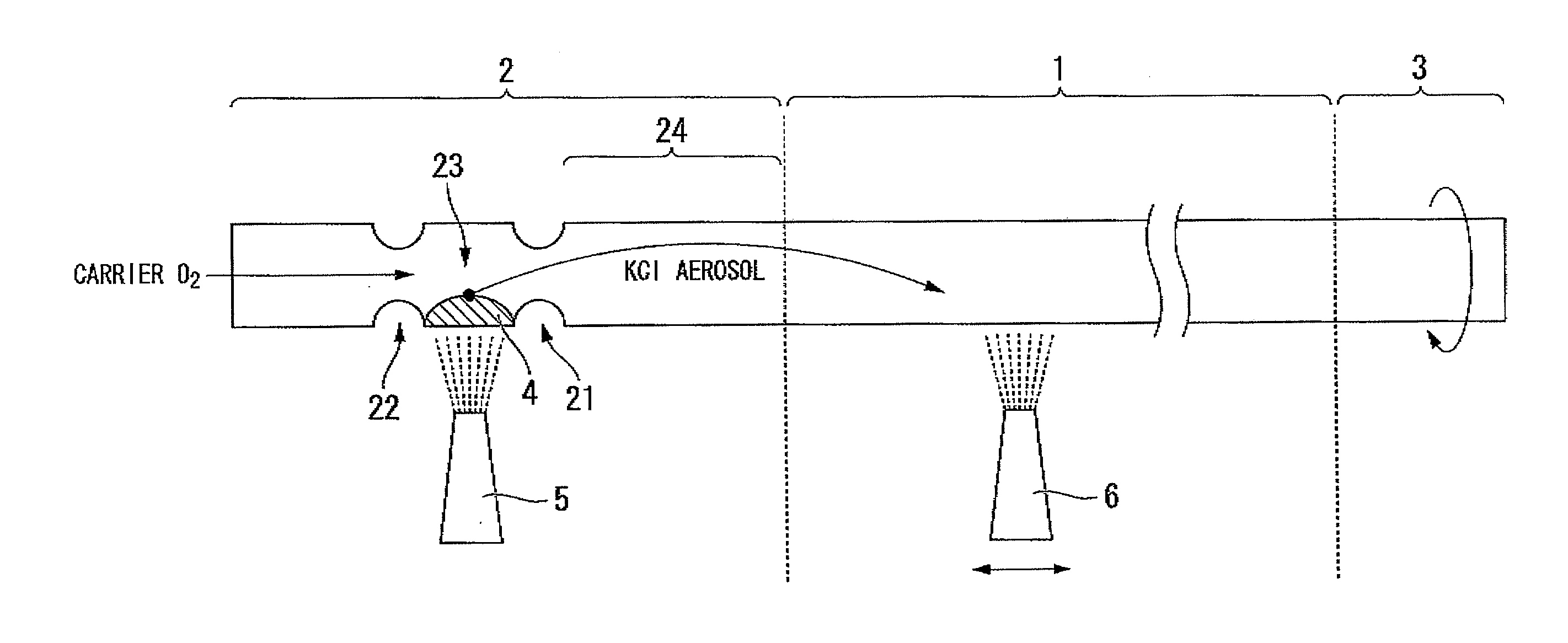
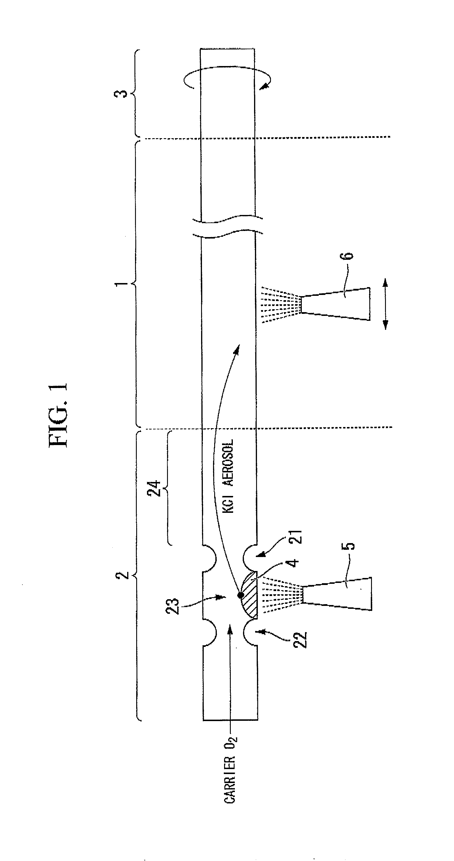
[0036]In the glass preform manufacturing method of the first aspect of the invention, it is possible to deposit an alkali metal compound or an alkaline earth metal compound on the rough surface of the glass element in a state of being particles while the heating of the alkali metal compound or the alkaline earth metal compound is not performed such that the temperature thereof reaches the melting point of glass.
[0037]Consequently, since the step of heating the glass preform (glass element) at a high temperature is only performed in the step of processing the glass element, it is possible to reduce the temperature in the step of manufacturing the glass preform.
[0038]Additionally, in addition to the foregoing effect, simply by forming the rough surface possessing a predetermined surface roughness on the inner surface of the glass element, highly-concentrative alkali metal compound or alkaline earth metal compound can be doped in the glass preform while being diffused therein, and it is possible to manufacture the glass preform in which the dopant concentration is accurately controlled.
[0039]In the glass preform manufacturing method of the second aspect of the invention, as a glass element on which an alkali metal compound or an alkaline earth metal compound is to be deposited, a glass tube section having a smooth inner wall face is prepared.
[0040]Furthermore, the rough surface is formed on the inner wall by depositing silica particles on the inner surface of the glass tube section.
[0041]Due to forming the rough surface, the specific surface of the inner wall face increases.

Problems solved by technology

However, a technique for industrially mass-producing such optical fibers is incomplete.
Accordingly, since the salts which become gas are hardly formed, it is difficult to apply the salts to the manufacture of optical fibers.
Additionally, in the above-described method of forming composite salts with higher vapor pressure and introducing the composite salts as vapor, the degree of rise in the vapor pressure is small, and the advantage is very restricted.
Since some extra chemical species which are ordinary unnecessary for the function of an optical fiber are added in the manufacturing method, there is a concern that a rise in the transmission loss is brought about.
Moreover, the method of strongly heating an alkali metal compound or an alkaline earth metal compound and obtaining alkali metal vapor or alkaline earth metal vapor has an indefinite reaction mechanism of a reduction reaction, and is deficient in practice.

Method used


Image

  • Glass preform manufacturing method
  • Glass preform manufacturing method
  • Glass preform manufacturing method

Examples


experiment 1

[0212](Experiment 1)

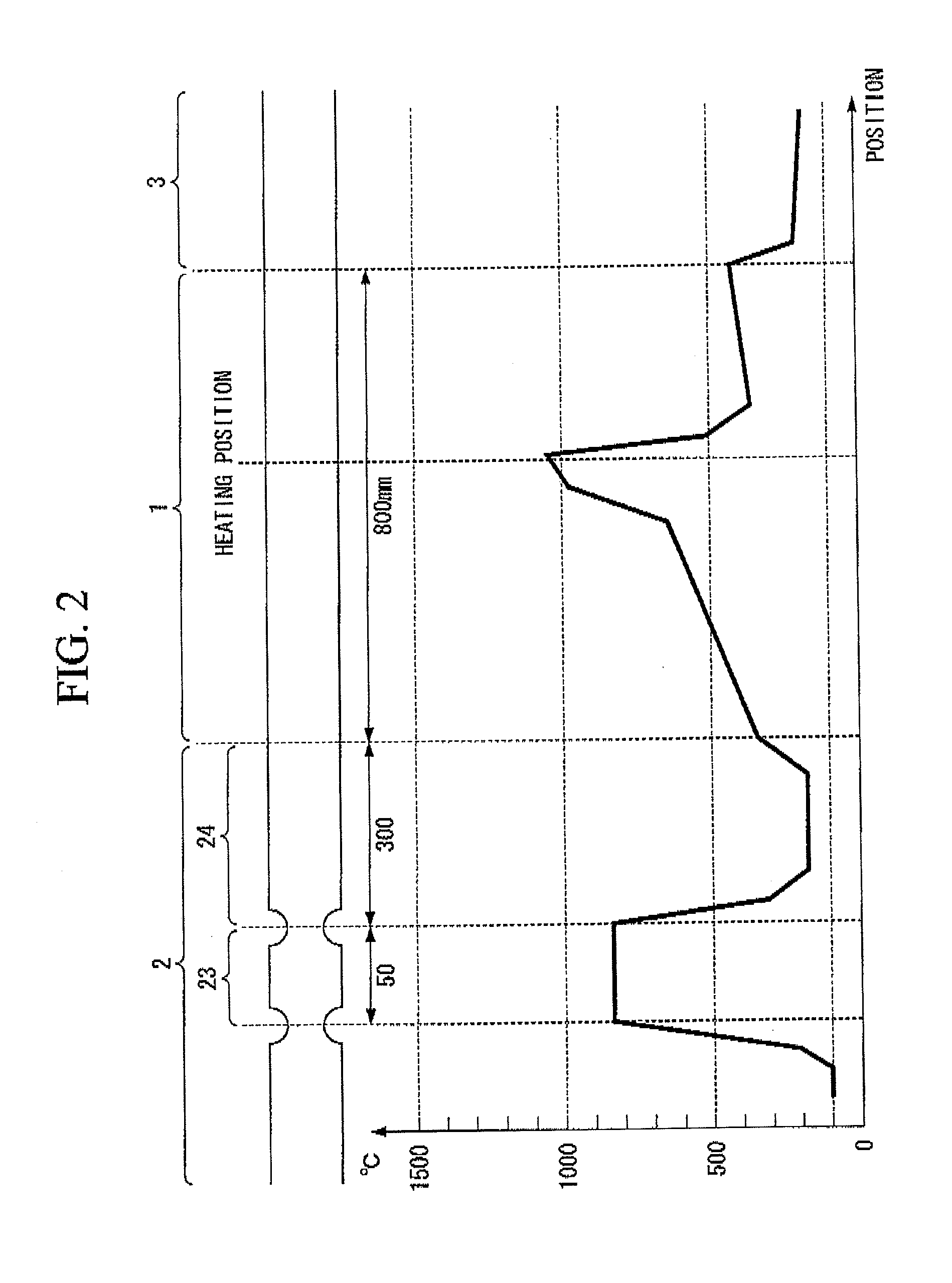
[0213]A glass tube (Suprasil-F300 made by Shin-Etsu Quartz Products Co., Ltd.) made of pure synthetic silica glass which contains a hydroxyl group of less than 1 ppm, iron ions of less than 0.005 ppm, and aluminum ions of less than 0.05 ppm, and has an external diameter of 32 mm, a thickness of 2.5 mm, and a length of 800 mm was adopted as the glass tube section 1.

[0214]This glass tube is transparent, and the inner surface and outer surface thereof is smooth.

[0215]Additionally, two dummy tubes made of pure synthetic silica glass, each of which has a length of approximately 500 mm and has the same external diameter and thickness as those of the glass tube section 1 were adopted as the first dummy tube section 2 and the second dummy tube section 3.

[0216]Both ends of a composite glass tube in which the glass tube section 1, the first dummy tube section 2, and the second dummy tube section 3 were integrated were attached to an MCVD glass forming lathe.

[0217]Additiona...

experiment 2

[0240](Experiment 2)

[0241]Traverse of the second oxyhydrogen burner 6 to be used for the heating of the glass tube section 1 was performed 5 times, and a glass preform was manufactured similarly to Experiment 1.

experiment 3

[0242](Experiment 3)

[0243]Traverse of the second oxyhydrogen burner 6 to be used for the heating of the glass tube section 1 was performed 10 times, and a glass preform was manufactured similarly to Experiment 1.


PUM

PropertyMeasurementUnit
Temperatureaaaaaaaaaa

Abstract

A glass preform manufacturing method, includes: preparing a glass element having a rough surface; turning a raw material of an alkali metal compound or a raw material of an alkaline earth metal compound into particles; depositing particles of the alkali metal compound or the alkaline earth metal compound on the rough surface of the glass element; oxidizing the particles of the alkali metal compound or the alkaline earth metal compound while diffusing alkali metal oxide or alkaline earth metal oxide in the glass element; and manufacturing a glass preform into which the alkali metal oxide or the alkaline earth metal oxide is doped.

Description

CROSS-REFERENCE TO RELATED APPLICATION[0001]This application is based on and claims priority from Japanese Patent Application No. 2010-206612 filed Sep. 15, 2010, the contents of which are incorporated herein by reference.BACKGROUND OF THE INVENTION[0002]1. Field of the Invention[0003]The present invention relates to a glass preform manufacturing method, which can accurately control the dopant concentration with low consumption of energy, and particularly, to a glass preform manufacturing method which is adapted to manufacture a low-loss optical fiber.[0004]2. Background Art[0005]Optical fibers produced using silica glass in which alkali metal oxide or alkaline earth metal oxide is doped has been shown by a number of predecessors to reduce the transmission loss thereof.[0006]However, a technique for industrially mass-producing such optical fibers is incomplete.[0007]In order to use a hydrolysis reaction or a thermal oxidation reaction caused by oxygen in gaseous phase in a conventio...

Claims


Application Information

Patent Timeline
IPC IPC(8): C03B37/012
CPCC03B37/01807C03B2201/54C03B2201/50
Inventor KITAMURA, TAKAYUKI
Owner THE FUJIKURA CABLE WORKS LTD
Learn More