Process for molding of a detergent composition

a technology of detergent composition and process, which is applied in the field of detergent composition molding, can solve the problems of residual detergent left on the die halves, poor or even non-release of the bars from the die surface, visible imperfections on the bar surface, and wet cracking along the plane, so as to reduce the operating temperature and save the operation. operation cost, the effect of preventing blockag

Inactive Publication Date: 2001-05-01
LEVER BROTHERS
View PDF26 Cites 29 Cited by
  • Summary
  • Abstract
  • Description
  • Claims
  • Application Information

AI Technical Summary

Benefits of technology

It is a particular advantage of the present invention that the detergent composition can enter the mould at a lower temperature than in a simple casting technique. When heating solid detergent compositions, less heat (i.e. energy) may be required as the operating temperatures can be lower. When cooling liquid detergent, no heating may be required at all. The present invention therefore offers economy in operation.
Typically, the detergent composition may be at a temperature of 60.degree. C. or less.
The present invention is particularly suited to detergent compositions which undergo supercooling, i.e. thermal energy can be removed outside the mould without the final bar structure forming.
Injection moulding is a process which is presently particularly used in the moulding of synthetic polymeric thermoplastic articles, particularly thermoplastic articles having thin cross sections and complex shapes.
In essence, an injection moulding apparatus for plastic material comprises a substantially closed mould and a means for delivering the plastic material under raised pressure into the substantially closed mould. Preferably there are means for raising the temperature of the plastic material to a temperature where the material is flowable under pressure. The process of the present invention can be carried out using such known injection moulding apparatus, with or without any means for heating the feed. Preferred modifications according to the present invention are discussed below.
A high temperature may be maintained near the point at which detergent composition is fed into the mould, so as to prevent blockage due to solidification.

Problems solved by technology

A problem encountered with the stamping process is die-blocking, in which amounts of residual detergent left on die halves build up during continued use of the dies.
Die blocking can lead to poor or even non-release of the bars from the die surface and / or visible imperfections on the bar surface.
They also tend to form cleavage planes within the bar, which weaken the bar and, with the repeated wetting and drying of the bar in use, can lead to wet-cracking along the planes.
Wet-cracking is highly undesirable being both unsightly and leading to bar fracture.
Certain detergent formulations are viscous liquids or semi-solids at commercially realistic elevated temperatures and therefore do not lend themselves to casting.
Furthermore, in the casting process, the detergent melt tends to cool slowly and unevenly.
This can lead to unwanted structural orientations and segregation of ingredients.
A major problem with the casting process is that detergent compositions in the moulds tend to shrink as they cool.
This is highly undesirable as the mould is intended to impart a distinctive shape on the bar and / or a logo of some kind.
However, no specific shear rates are given for this viscosity range.
Pressures which are too high are described as causing splashing in the mould and as increasing the density of the melt.
Furthermore, it is taught that detergent fluid mixtures in the neat or middle (anisotropic liquid) phases are not suitable for closed die moulding because of the excessive viscosity of these phases and the tendency for undesirable complexes to form in these phases.
However, the solution described has several inherent drawbacks, most of which are common to the casting and framing processes.
It is very energy intensive, energy being required to heat the detergent compositions to the high temperatures at which the fluid mixture is injected and subsequently to cool the moulds in order to reduce the solidifying times to acceptable levels.
Furthermore, by injecting the compositions as high temperature fluids, the process leads to problems with shrinkage of the bars as they solidify.
It also fails to address the problem of segregation of ingredients as the detergent composition cools in the mould.
Some detergent compositions may be made permanently sticky if they are injection moulded under the wrong conditions.
That is, some solid detergent compositions have a complex molecular structure which may be disrupted if the solid is exposed to excessive shearing stresses.
Configurations such as severe bends, constrictions and fast moving parts may subject the detergent composition to high shear.
In contrast, detergent compositions in particulate form may be sticky and flow relatively poorly.
There are particular problems with fluid detergent compositions.
It has been found that there can be a problem in simple filling with jetting or "snaking" of the material in the mould.
One of the problems associated with benefit agents is that they are washed away by the lathering surfactants before they are deposited on the skin.
In a fluid system, it is difficult to stabilise droplets of a specific size.

Method used


Image

  • Process for molding of a detergent composition
  • Process for molding of a detergent composition
  • Process for molding of a detergent composition

Examples


example 1

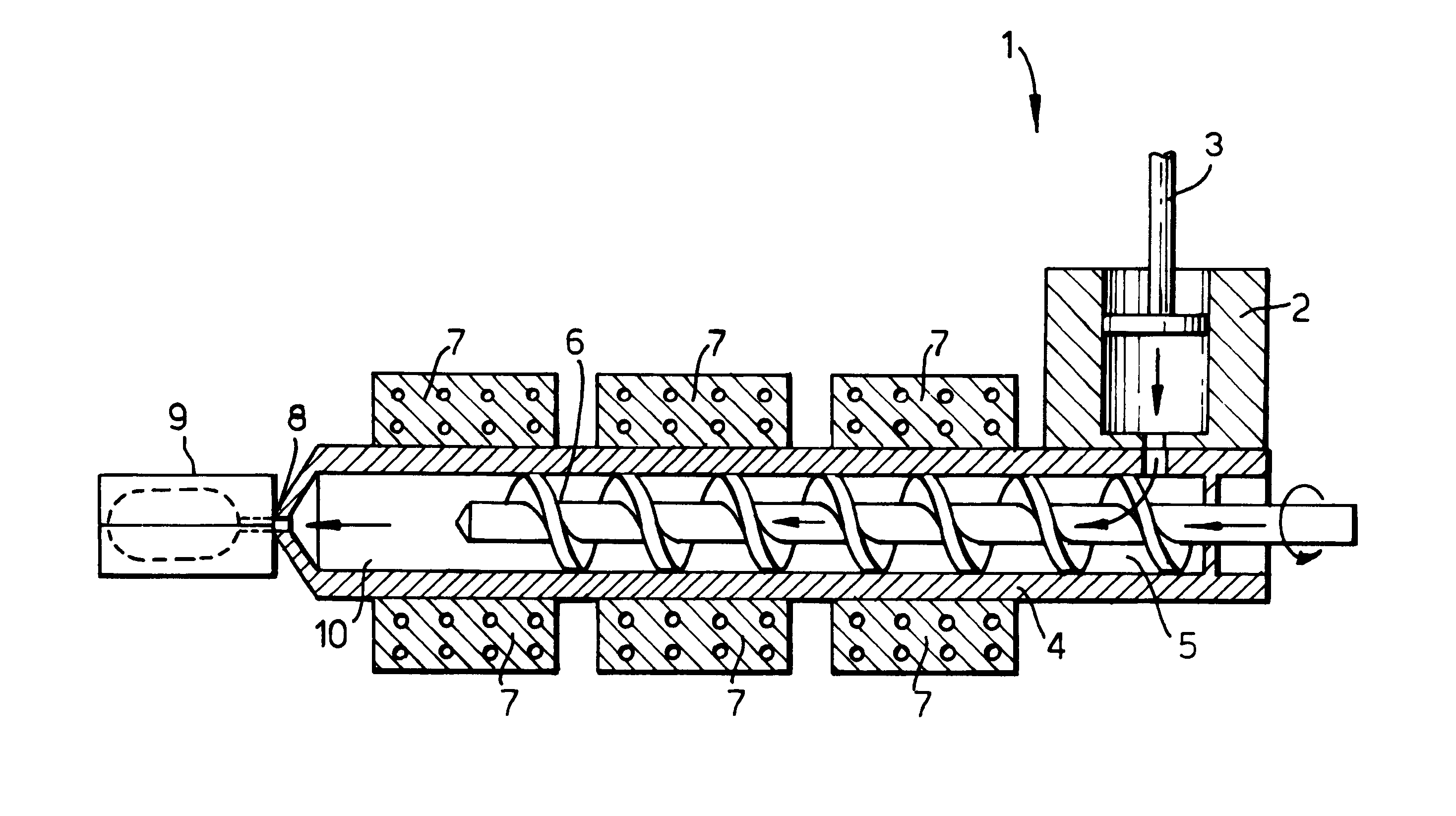
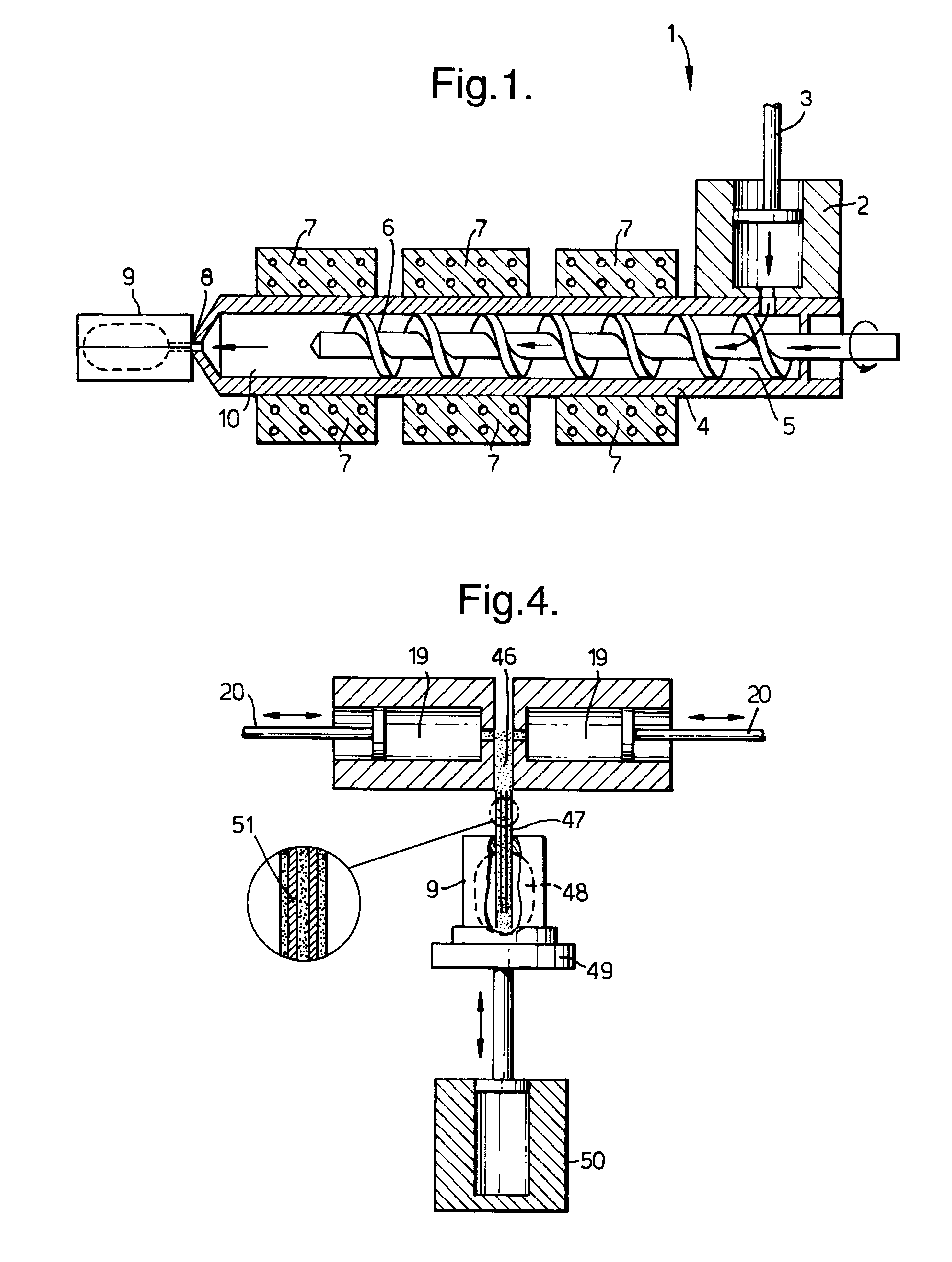
A reciprocating screw injection moulding unit according to FIG. 1 sold as the "SANDRETTO Series 7 HP135" having three temperature controlled zones was used. The machine was fitted with a 50 mm diameter dough moulding compound screw and barrel. The feed means comprised a conventional stuffing pot, or manual feed as appropriate to the material. A screw rotation rate of 80 to 100 rpm was used.

The mould (9) comprised a pair of aluminium mould parts defining a bar shape. These were as those conventionally used in die stamping of detergent bars, modified by the addition of a feed hole sized to take the nozzle, and small holes at appropriate places in the mould to allow air to vent during filling.

Detergent formulations A, B and C were injection moulded.

Formulation B comprised white milled, commercially available UK Lux soap dated September 1996. Formulation C comprised milled commercially available Dove beauty bar dated June 1996.

A detergent composition was fed into the stuffing pot in the...

example 2

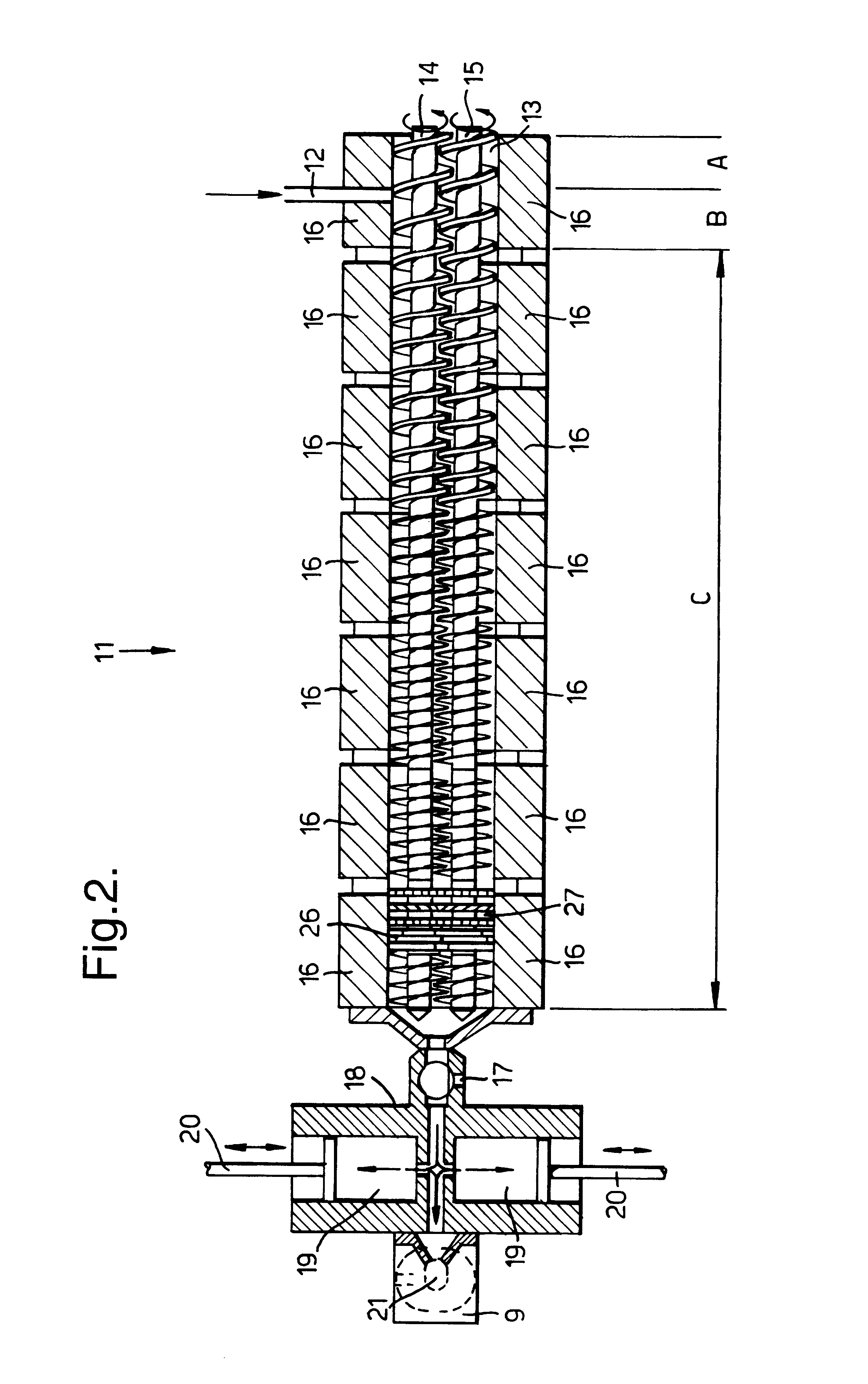
An apparatus according to FIG. 2 comprising a BETOL co-rotating twin screw extruder with 40 mm diameter screws and eight temperature control zones was used. The temperatures of the connection valve 17 and the injection head assembly (18,19,20) was also controlled.

A novel piston type injection unit according to the present invention was fitted at the end of the screw extruder. Detergent compositions as set out below were prepared in molten form and fed to the extruder using a Bran and Luebbe metering pump. The molten feed was at a temperature of 90 to 95.degree. C. It was maintained in a stirred, heated feed pot.

During filling the mould was moved either manually, or hydraulically using a mould moving mechanism according to FIG. 4 of the present application.

Detergent formulations D and E were injection moulded.

The apparatus was used to form detergent bars over a range of temperatures which were subsequently released from the moulds and checked for mould release properties and surface ...

example 3

An apparatus comprising a BETOL co-rotating twin-screw extruder with 40 mm diameter screws, eight temperature controlled zones, and a low shear, in-line injection head was used as depicted in FIG. 3. Detergent composition E was prepared in molten form (95.degree. C.) and held in a stirred, heated feed pot. It was then fed into Zone E of the extruder using a Bran & Luebbe metering pump. Detergent composition B was fed at ambient temperature to zone D as 4 mm diameter noodles using a Ktron feeder. The maximum injection pressure and the holding time were recorded. The results are given in Table 3.

The detergent compositions were in a semi-solid state when they entered the mould. In all the runs, the mould was at ambient temperature before fill and cooling was effected by packing solid CO.sub.2 around the outside of the mould for the period of time specified plus maintaining the mould at ambient temperature for a further 5 minutes.

These runs illustrate that the surface quality of the bar...


PUM

PropertyMeasurementUnit
pressureaaaaaaaaaa
temperatureaaaaaaaaaa

Abstract

A process for forming detergent bars by injection moulding in which a pressure is applied to a partially structured detergent composition to deliver it to a mould. The detergent composition can be delivered to the mould in a substantially semi-solid state, at a temperature below 70° C. and at a pressure at the point of injection of greater than 20 psi. Apparatus for forming detergent bars according the invention are also described

Description

The present invention relates to a process and apparatus for forming detergent bars and detergent bars formed thereby. The detergent bars can be of the personal or fabric wash type.BACKGROUND AND PRIOR ARTDetergent bars are conventionally manufactured by one of two methods; (i) milling followed by extrusion ("plodding") and stamping (sometimes referred to as the "milling" process), or (ii) casting.In the milling process, a preformed solid composition comprising all components of the bar is typically plodded, i.e. extruded through a nozzle to form a continuous "rod" which is cut into smaller pieces of predetermined length, commonly referred to as "billets". These "billets" are then fed to a stamper or, alternatively, are given an imprint on one or more surfaces using, for example, a die of the same dimensions as the bar surface which is hit with force such as with a mallet or a die in the shape of a roller, or simply cut.There are several shortcomings associated with the milling meth...

Claims


Application Information

Patent Timeline
Patent Type & Authority Patents(United States)
IPC IPC(8): C11D13/16C11D13/00C11D13/18C11D17/00C11D17/06B29C
CPCC11D13/16C11D13/18C11D17/0052C11D17/0069C11D17/00
Inventor ALLAN, PETER STEWARTCORDELL, JOHN MARTINIRVING, GRAEME NEILNADAKATTI, SURESH MURIGEPPANAIK, VIJAY MUKUNDOVERTON, CHRISTINE ANNSTOCKER, FREDERICK EDMUNDTARVERDI, KARNIKWAHLERS, JOHN COLIN
Owner LEVER BROTHERS
Why Eureka
Try Eureka