Drill Bit with High Performance for Chip Removal

Inactive Publication Date: 2008-07-10
JIANGSU TIANGONG TOOLS CO LTD
View PDF28 Cites 30 Cited by
  • Summary
  • Abstract
  • Description
  • Claims
  • Application Information

AI Technical Summary

Benefits of technology

[0006]In view of the above problems, this utility provides a drill bit to effectively solve the above problems, for instance, improving chip removal to enable the cutt

Problems solved by technology

1. Values of front angles of different points on the main cutting edge vary significantly and the front angles become negative around the drill core, leading to poor cutting conditions.
2. The chisel edge is too long with a very large cutting edge angle, which is a very large negative front angle, le

Method used


Image

  • Drill Bit with High Performance for Chip Removal
  • Drill Bit with High Performance for Chip Removal
  • Drill Bit with High Performance for Chip Removal

Examples


Example

EXAMPLE 1

[0022]As shown in FIGS. 1 and 2, polish the tooth 4 on the drill tip of a conventional twist drill to obtain two symmetrical crescent circular grooves and a trapezoidal main cutting edge face 3 between the tooth and the back groove edge 5 to form a 3-tip, 7-edge’ shape with recessed drill tip and two side tips existing together, further polish the back groove edge 6 to form the secondary back face 7, which interests drill core 1 and the tooth 4 and polish the tooth at the intersection between the secondary back face and the drill core& tooth to form the tooth plane so that the angle between the secondary back face and the tooth plane is 60 degrees.

Example

EXAMPLE 2

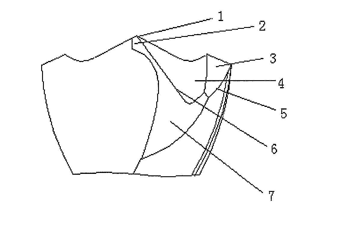
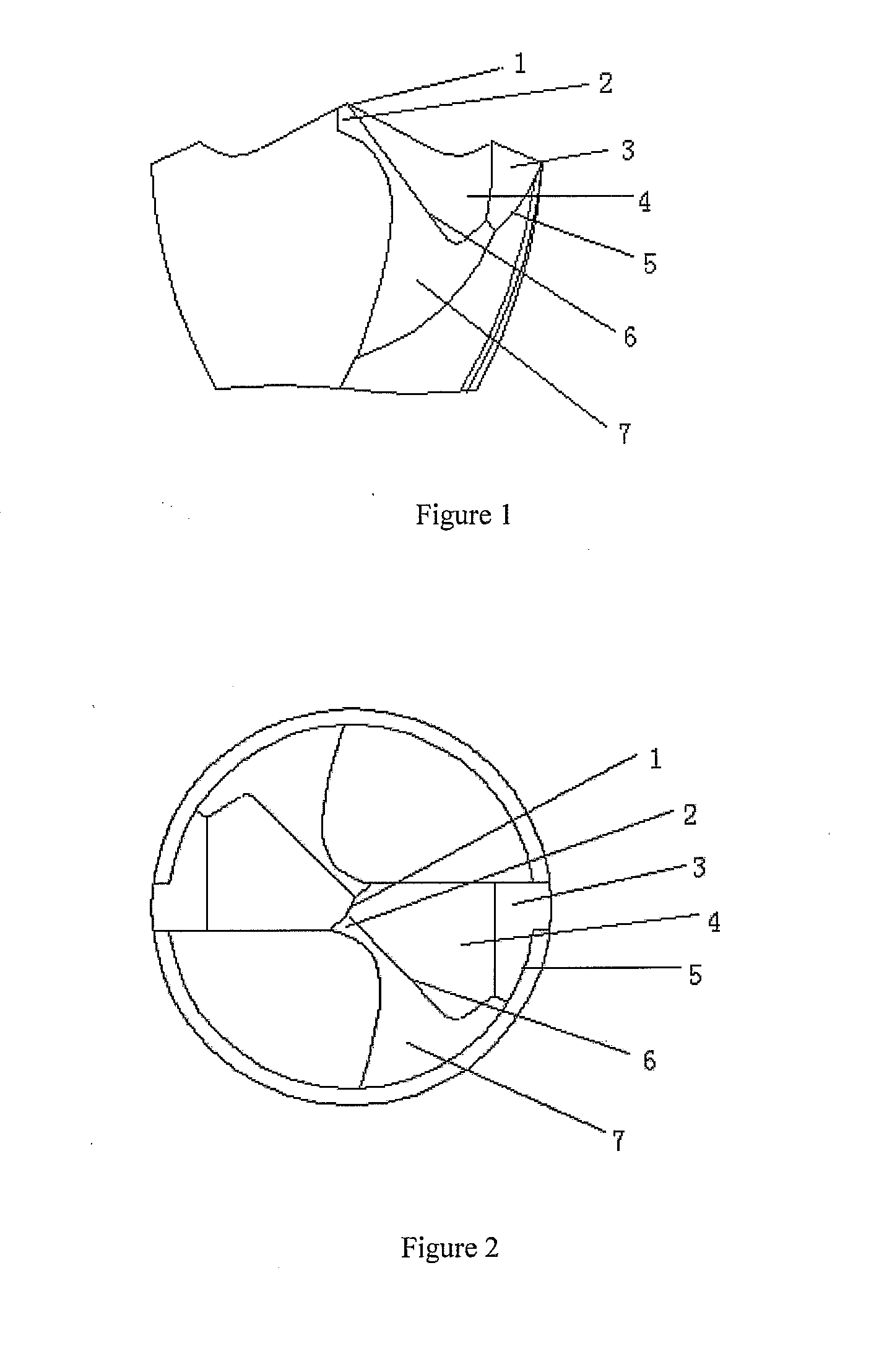
[0023]A drill bit with high performance for chip removal same as example 1 except the main cutting edge face between said tooth face and said back edge is a triangle.

Example

EXAMPLE 3

[0024]A drill bit with high performance for chip removal same as example 1 except that the angle between said secondary back face and said tooth plane is 120 degrees.


PUM

PropertyMeasurementUnit
Angleaaaaaaaaaa
Shapeaaaaaaaaaa

Abstract

A drill bit with high performance for chip removal. The drill bit comprises a cutting tip and a drill body. The cutting tip comprises a chisel edge, a back edge, a cutting edge groove and a rear rib. The cutting edge groove is a circular groove having meniscus shape. A primary cutting surface interposed between the cutting edge groove and the back edge has a trapezoidal or triangular shape. Grinding the rear rib forms a quadratic rear plane. The quadratic rear plane crossing with the chisel edge and the cutting edge groove defines a cutting edge groove plane. The drill bit has three tips and seven cutting edges. A drill bit according to the present invention provides a significant improvement in cutting performance over known twist drill bit in the prior art.

Description

TECHNICAL FIELD[0001]This utility relates to a processing tool. More particularly, this utility relates to a metal processing tool, to be specific, a drill bit with high performance for chip removal.BACKGROUND OF THE INVENTION[0002]There has been little in the structure and shape of conventional twist drill during the past 100 years or more following its birth; with the continuous development of science and technology and mushrooming of new materials, higher requirements are imposed on solid drilling. However, conventional twist drills suffer from the following main problems:[0003]1. Values of front angles of different points on the main cutting edge vary significantly and the front angles become negative around the drill core, leading to poor cutting conditions.[0004]2. The chisel edge is too long with a very large cutting edge angle, which is a very large negative front angle, leading to poor cutting conditions. Hence, the axial resistance is large and the centering is not good.[0...

Claims


Application Information

Patent Timeline
IPC IPC(8): B23B51/00
CPCB23B51/02B23B2251/085B23B2251/14Y10T408/899B23B2270/30Y10T408/905Y10T408/9097B23B2251/18
Inventor ZHU, XIAOKUN
Owner JIANGSU TIANGONG TOOLS CO LTD
Why Eureka
Try Eureka