

OSNR monitoring method and apparatus using tunable optical bandpass filter and polarization nulling method
- Summary
- Abstract
- Description
- Claims
- Application Information
AI Technical Summary
Benefits of technology
Problems solved by technology
Method used
Image


Examples
first embodiment
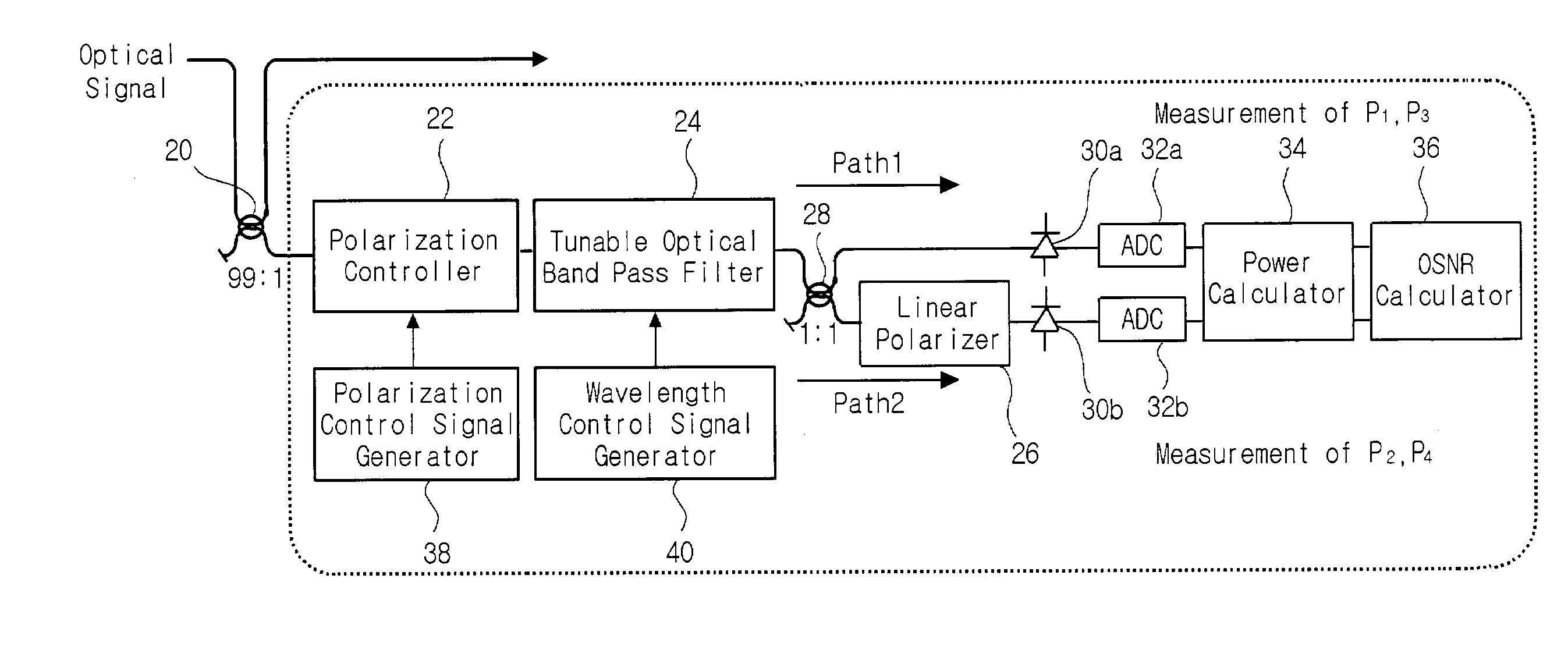
[0034]FIG. 4 illustrates the principle of an optical signal to noise ratio (OSNR) monitoring method according to the present invention, and FIG. 5 shows an OSNR monitoring apparatus according to the present invention.
[0035]A portion of an optical signal traveling through a wavelength division multiplexing (WDM) optical communication network and including an amplified spontaneous emission (ASE) noise is separated by a 99:1 directional coupler 20 and then used for measuring an OSNR. The 99:1 directional coupler 20 extracts a portion of the optical signal, which has a 1 / 100 intensity of the optical signal including the ASE noise, and then inputs the extracted portion of the optical signal into a polarization controller 22.
[0036]The polarization controller 22 receives a polarization control signal from a polarization control signal generator 38 and adjusts the polarization state of the optical signal so that the intensity of the optical signal including the ASE noise being output from t...
second embodiment
[0056]FIG. 6 is a view showing the OSNR monitoring apparatus according to the present invention.
[0057]The 99:1 directional coupler 20 extracts a portion of the optical signal, which is 1 / 100 times as large as the intensity of the optical signal including the ASE noise, and then inputs the extracted portion of the optical signal into the polarization controller 22.
[0058]The polarization controller 22 receives polarization control signal from the polarization control signal generator 38 and operates so that the optical signal being output from the polarization beam splitter 42 is separated into two optical signals with polarization components that are orthogonal to each other. That is, an optical signal having a polarization state identical to the polarization state of the polarization controller 22 proceeds along path 3. An optical signal having a polarization state orthogonal to the polarization state of the polarization controller 22 proceeds along path 4.
[0059]Generally, it is req...
PUM
 Abstract
Description
Claims
Application Information