Load-sensing mechanism for aerial work apparatus

Inactive Publication Date: 2004-12-30
MAN ELEVATOR MFG
View PDF6 Cites 31 Cited by
  • Summary
  • Abstract
  • Description
  • Claims
  • Application Information

AI Technical Summary

Benefits of technology

0012] Another object of this invention is to provide a novel load-sensing mechanism for use on an aerial work apparatus that directly measures the load on the platform of the apparatus in a highly accurate fashion regardless of the position or configuration of the boom supporting that platform.
0013] Another object of this invention is to provide an improved load-sensing mechanism for use on an aerial work apparatus that accurately measures the load on the platform of the apparatus regardless of the exact location of that load upon the platform, whether all or some of that load overhangs the platform, or whether that load is not at rest with respect to the platform.
0014] Another object of this invention is to provide an exceptional load-sensing mechanism for use on an aerial work apparatus that dir

Problems solved by technology

Exceeding this rated capacity technically risks overcapacity since any greater load is presumed capable of causing the apparatus to overturn.
A single capacity for the platform has long been a convenient safety parameter since keeping the lifted load under this figure was a simple way of avoiding the possibility of overcapacity regardless of boom position or boom length The drawback with this approach is that platform capacity varies not only with the load at the end of the boom but also with the boom's degree of elevation and range of extension.
In particular, the size of load that can be safely lifted can exceed the rated capacity by simply not fully extending the boom.
As a consequence, full advantage of such equipment is never achieved because the usefulness of the machine has been intentionally diminished.
Even though these charts would often

Method used


Image

  • Load-sensing mechanism for aerial work apparatus
  • Load-sensing mechanism for aerial work apparatus
  • Load-sensing mechanism for aerial work apparatus

Examples


Example

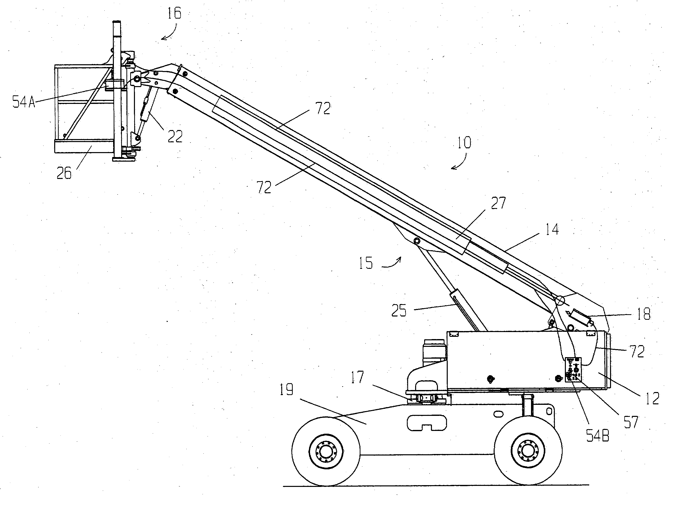
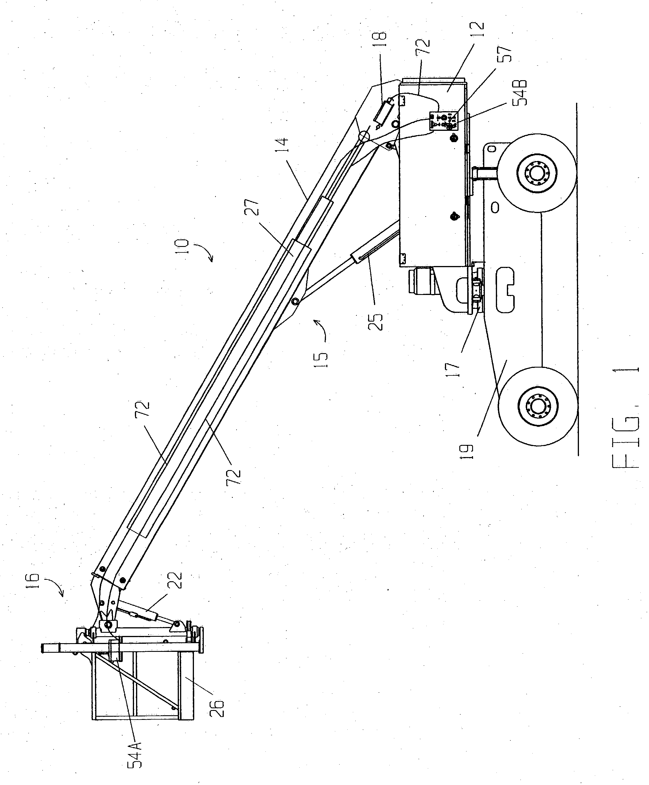
[0034] The drawings illustrate an improved aerial work apparatus 10 in accordance with this invention. As seen in FIG. 1, aerial work apparatus 10 is comprised of a base 12, a boom 14 securely mounted to base 12, and a platform 16 pivotably attached to the outer or distal end of boom 14.

[0035] Boom 14 is capable of three-dimensional movement in a fashion known to those skilled in the art. Boom 14 can rotate 360.degree. in either direction in a horizontal plane through the associated rotation of base 12 about base pivot 17. Base pivot 17 is either mounted on the bed of a trailer (not shown) when base 12 is vehicle-mounted or mounted on wheel platform 19 when base 12 is self-propelled as shown in FIG. 1.

[0036] Boom 14 can also be selectively raised and lowered to a position measured by the angle formed by boom 14 with a plane parallel to the ground by means of hydraulic boom lift cylinder 25. Furthermore, boom 14 can be telescopically extended or retracted axially by means of hydrauli...


PUM


Abstract

An aerial work apparatus having a boom mounted to a base, a platform attached to the distal end of the boom, a boom mechanism for positioning the platform, a boom control module mounted with respect to the platform, a vertical load-sensing mechanism mounted at the platform for measuring the platform load and generating a load signal based on that measurement, and a controller operationally attached to the boom mechanism and boom control module. The controller receives the load signal and at least one position signal relating to the position of the platform and generates at least one control signal based thereon. The boom mechanism is controlled by the boom control module through the controller. Preferably, the load-sensing mechanism is held in position by a vertical support column attached at the distal end of the boom so that the mechanism fully supports a platform support member attached to the platform.

Description

[0001] This invention is related generally to aerial work apparatus and, more particularly, to aerial work apparatus having load-sensing mechanisms to measure the load on a platform attached to the distal end of a boom.[0002] Various types of aerial work apparatus are well known as excellent tools for lifting workers or material upon a platform to elevated and oftentimes obstructed locations. Such equipment is provided with an extendable boom that can be rotated about its counter-weighted base as well as elevated to varying angles off the ground. The platform is commonly provided with a work basket to hold workers and material but it may instead consist of a material-handling mechanism such as a winch or fork-lifting tines.[0003] Each model of this line of apparatus typically has a rated capacity for the load it may carry at the distal end of the boom. This rated capacity is based on safety standards to arrive at a prescribed limit for the load to be carried whenever the boom is sub...

Claims


Application Information

Patent Timeline
IPC IPC(8): B66F11/04B66F17/00
CPCB66F11/046B66F17/006
Inventor BAILEY, JEFFREY H.
Owner MAN ELEVATOR MFG
Why Eureka
Try Eureka