System and method for processing image data relative to a focus of attention within the overall image

a processing system and image data technology, applied in the field of machine vision systems, can solve the problems of large processing overhead, inability to meet the required throughput rate and other system parameters, and the movement of data is expensive in terms of processing overhead, so as to save processing time and data storage overhead, and achieve high accuracy and fine alignment process

Inactive Publication Date: 2011-09-01
COGNEX CORP
View PDF57 Cites 41 Cited by
  • Summary
  • Abstract
  • Description
  • Claims
  • Application Information

AI Technical Summary

Benefits of technology

[0012]In another embodiment, the system and method is employed for coarse alignment / fine alignment tasks. A coarse alignment is performed by the alignment process in the first processor group, in which rough accuracy is employed using one or more patterns to identify the position of one or more objects and / or surface features in the image. This rough accuracy can be at the pixel or approximately ½ pixel level in an exemplary implementation. This coarse alignment step saves processing time and data storage overhead normally associated with a single-step fine-alignment process. The coarse alignment process thereby provides data for the approximate (coarse) position of the identified pattern of object(s) or feature(s) in the in the acquired image so as to identify the location of the respective object(s) or feature(s) in the image. The data relevant to located the coarse-alignment position, and associated data (and feature information usable in other processes), is forwarded to the off-die second processor. Image data can also be provided concurrently to the second processor as it is read-out from the sensor. The second processor uses the data to perform a fine alignment process on the overall image data, which is advantageously focused upon the regions of the image that have been coarsely aligned. In general a region of interest can be drawn around these regions (for example a boundary of one to a few pixels), and the fine alignment process uses one or more patterns to operate on each region to derive a highly accurate (for example, one-tenth of a pixel and one-tenth of a degree of rotation, or finer) alignment value. The ability to concentrate fine alignment on the regions of the overall image that contain one or more coarsely aligned objects or features allows the fine alignment process to occur more quickly and efficiently than if the entire image was finely aligned in one process step. The output value in this embodiment is finely accurate location of the position of the object(s) or feature(s) in multiple degrees of freedom.
[0013]In another embodiment, the system and method is employed for coarse / fine inspection of an object or surface. A less-precise inspection process is employed on the first processor group to quickly identify candidate results, which may include various false-positive identifications, as well as valid inspection results. The rapidity in which the first processor group can generate such results counterbalances the potential presence of false positives. The locations and other data for feature candidates are transferred to the second processor, which includes a more-accurate inspection process (based, for example, on synthetic or actual trained image data). The inspection process focuses attention upon the candidates rather than the entire image, thereby reducing latency overhead. The output value is the inspection result (e.g. part passed, part defective, part-in / out-of-tolerance).

Problems solved by technology

This typically requires the device to handle a very large quantity of data, and thus can invoke significant processing overhead.
This movement of data is expensive in terms of processing overhead.
These various issues lead to a scenario in which the DSP may be too overloaded with image data to meet required throughput rates and other system parameters.

Method used


Image

  • System and method for processing image data relative to a focus of attention within the overall image
  • System and method for processing image data relative to a focus of attention within the overall image
  • System and method for processing image data relative to a focus of attention within the overall image

Examples


Embodiment Construction

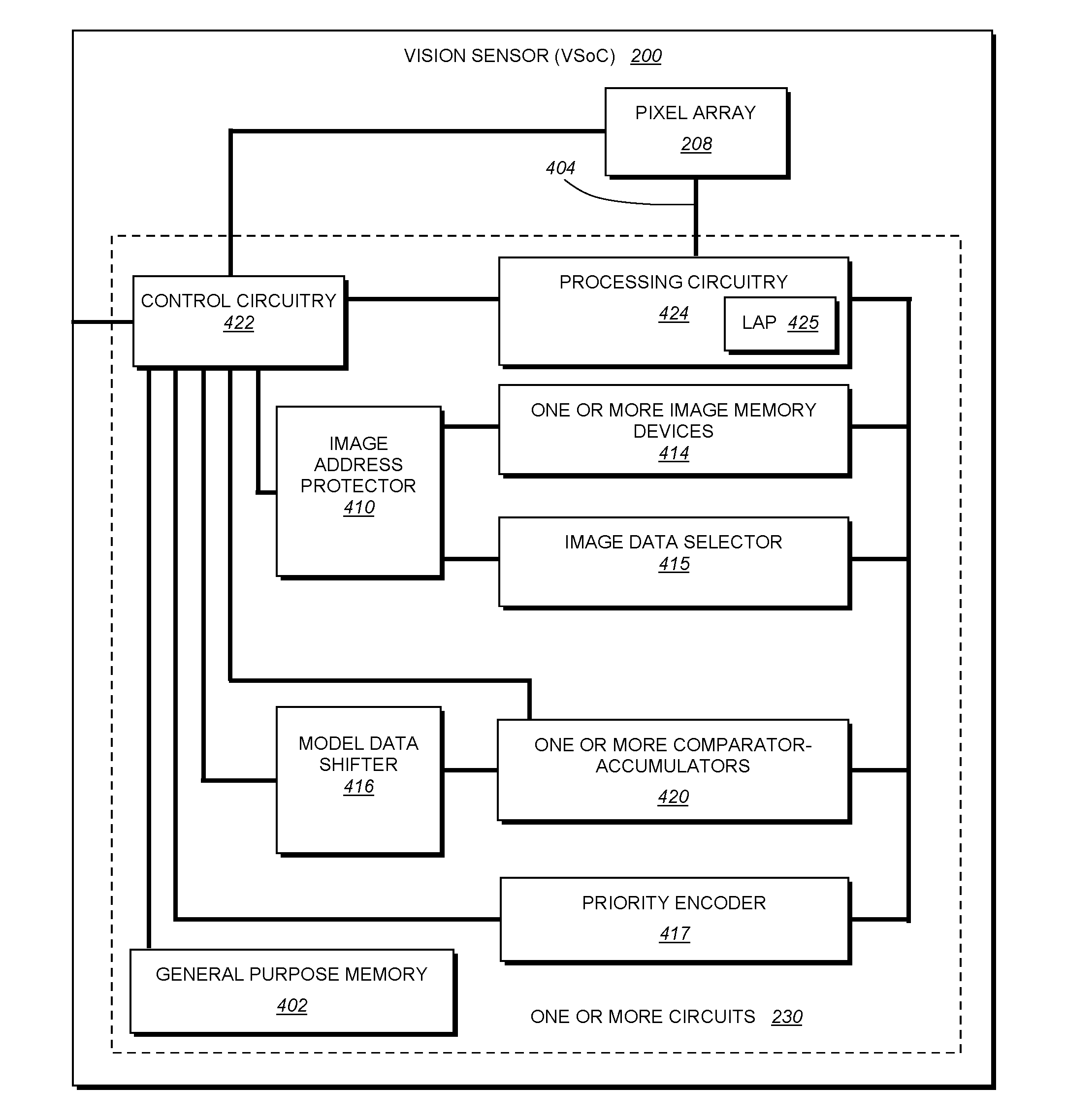
[0032]The illustrative system and method for processing discrete image data within an overall set of acquired image data, based upon a focus of attention, is adapted to operate with a vision system processor that defines an architecture capable of processing an entire row of data read-out from an interconnected pixel array in a discrete processing cycle (i.e. all data in a row being simultaneously processed with each clock cycle). To accomplish this, the overall processor is organized to include a wide on-bit data bus (for example a 1024×1 bus) between an image data storage memory (also having a storage array that is 1024 wide, and also termed herein a “data memory”) and the pixel array (in this example, a 1024×768 pixel array with 8-bit or 6-bit pixels). This memory is interconnected by another similarly wide (1024×1, for example) bus to the image processing component, which is organized to process the entire row simultaneously using, for example, single-instruction, multiple-data ...


PUM


Abstract

This invention provides a system and method for processing discrete image data within an overall set of acquired image data based upon a focus of attention within that image. The result of such processing is to operate upon a more limited subset of the overall image data to generate output values required by the vision system process. Such output value can be a decoded ID or other alphanumeric data. The system and method is performed in a vision system having two processor groups, along with a data memory that is smaller in capacity than the amount of image data to be read out from the sensor array. The first processor group is a plurality of SIMD processors and at least one general purpose processor, co-located on the same die with the data memory. A data reduction function operates within the same clock cycle as data-readout from the sensor to generate a reduced data set that is stored in the on-die data memory. At least a portion of the overall, unreduced image data is concurrently (in the same clock cycle) transferred to the second processor while the first processor transmits at least one region indicator with respect to the reduced data set to the second processor. The region indicator represents at least one focus of attention for the second processor to operate upon.

Description

RELATED APPLICATIONS[0001]This application is a continuation-in-part of copending U.S. application Ser. No. 12 / 184,187, filed Jul. 31, 2008, entitled VISION SENSORS, SYSTEMS, AND METHODS, the entire disclosure of which is expressly herein incorporated by reference, which claims the benefit of copending U.S. Provisional Application Ser. No. 60 / 991,545, filed Nov. 30, 2007, entitled VISION SYSTEM ON A CHIP, the entire disclosure of which is expressly herein incorporated by reference.FIELD OF THE INVENTION[0002]This invention relates to machine vision systems and more particularly to processing of image data by a vision system processing arrangement.BACKGROUND OF THE INVENTION[0003]Machine vision systems use image acquisition devices that include camera sensors to deliver information related to a viewed object / surface. The system then interprets this information according to a variety of algorithms to perform a programmed decision-making, alignment, and / or identification function.[0004...

Claims


Application Information

Patent Timeline
Patent Type & Authority Applications(United States)
IPC IPC(8): G06K9/00G06F15/80G06F9/02
CPCG06K9/00986H04N5/232G06T1/20G06K9/6203G06V10/955G06V10/7515
Inventor MOED, MICHAEL C.MCGARRY, E. JOHN
Owner COGNEX CORP
Why Eureka
Try Eureka