Method for fabricating super fine set of die for guiding light plate

A manufacturing method and light guide plate technology, applied in optics, nonlinear optics, microlithography exposure equipment, etc., can solve the problems of low pass rate, time-consuming and complicated process of depositing metal base 5, etc.

Inactive Publication Date: 2008-01-02
CORETRONIC
View PDF4 Cites 0 Cited by
  • Summary
  • Abstract
  • Description
  • Claims
  • Application Information

AI Technical Summary

Problems solved by technology

[0004] However, this method has the following disadvantages: the process of depositing the metal base 5 is time-consuming and has a low yield, and because it utilizes the electroforming process, the surface of the metal base 5 will be uneven, requiring secondary processing, making the process very difficult. complicated

Method used


Image

  • Method for fabricating super fine set of die for guiding light plate
  • Method for fabricating super fine set of die for guiding light plate
  • Method for fabricating super fine set of die for guiding light plate

Examples


Embodiment Construction

[0019] Relevant detailed description and technical contents of the present invention are as follows now in conjunction with the accompanying drawings:

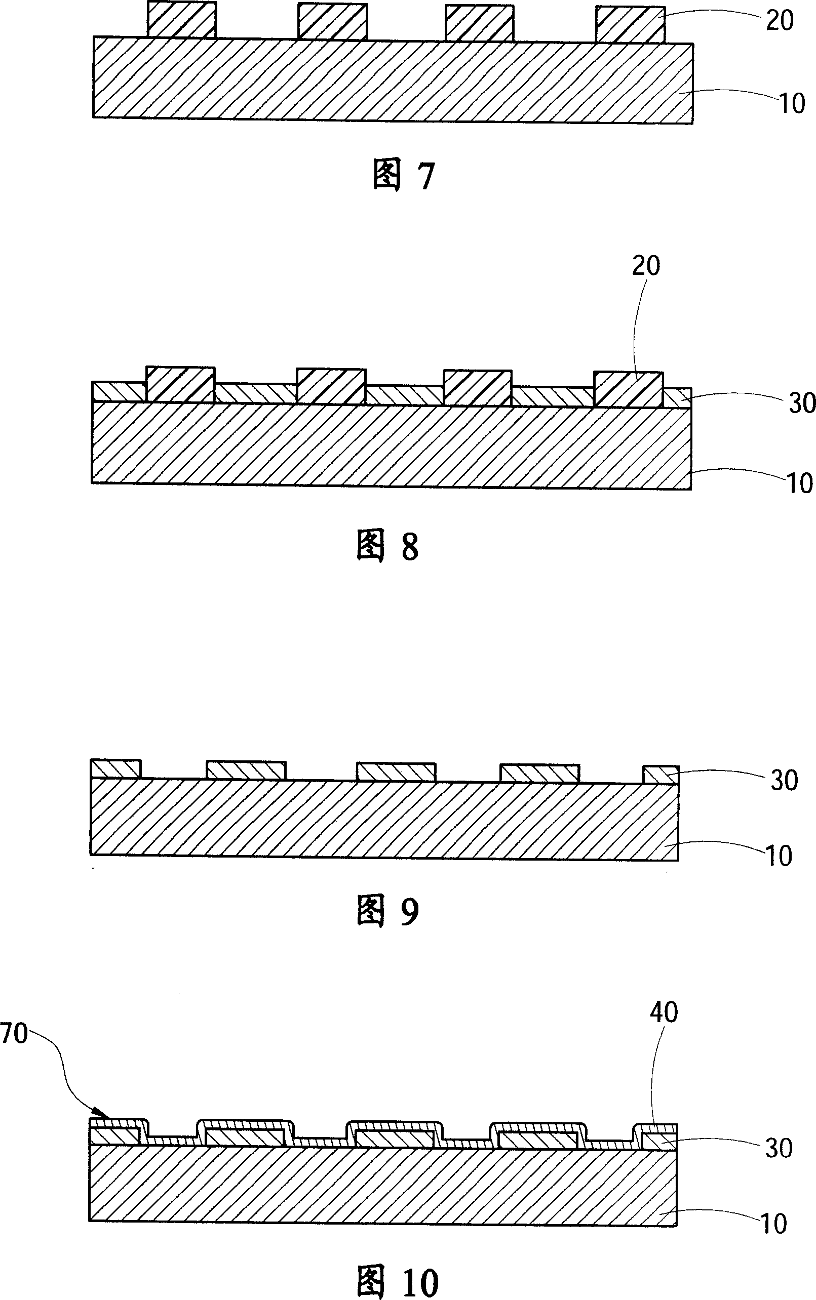
[0020] Please refer to FIG. 7 to FIG. 10 , which are cross-sectional views of making the mold core of the light guide plate at different steps according to the method of the present invention. The steps of the present invention include:

[0021] a. Form a non-metallic layer 20 with a specific pattern on the surface of a metal substrate 10 (as shown in FIG. 7 ), which is fabricated by a lithography process.

[0022] b. On the surface area of ​​the metal substrate 10 that is not covered by the non-metallic layer 20, a metal layer 30 with a thickness not greater than the thickness of the non-metallic layer 20 is plated by electroplating or electroless plating (as shown in Figure 8) ; Due to the characteristics of electroplating or electroless plating process, it can only deposit metal on the surface of metal, so it can only depos...


PUM


Abstract

A method for preparing light guide plate forms a patterned metal layer on a metal baseplate by utilizing the microimaging process, and then coats a Ni - P alloy layer on surface of the patterned metal layer which has height difference.

Description

technical field [0001] The invention relates to a method for manufacturing a mold core of a light guide plate, in particular to a method for manufacturing a mold core of a light guide plate with excellent surface characteristics in a non-printing manner. Background technique [0002] At present, the manufacturing method of light guide plate can be divided into printing method and non-printing method. The printing method is to distribute the printing materials of high-emission light source materials such as SiO2 and TiO2 on the bottom surface of the light guide plate by printing. , so that the light is guided from the front surface and evenly distributed in the light-emitting area; the non-printing method is to design the pattern on the mold core, and the light guide plate uses the mold core as the mold, and the pattern is directly produced on the light guide plate by injection molding , and use this pattern to direct the light to emit from the front view, and evenly distribu...

Claims


Application Information

Patent Timeline
Patent Type & Authority Patents(China)
IPC IPC(8): G02F1/1335G03F7/20
Inventor 刘明达侯仕骑
Owner CORETRONIC
Why Eureka
Try Eureka