Organic solar cell and method for manufacturing same

a solar cell and organic technology, applied in the direction of photovoltaic energy generation, semiconductor devices, solid-state devices, etc., can solve the problems of increasing the emission of carbon dioxide and other greenhouse gases into the air, reducing the economic feasibility of existing inorganic solar cells, etc., to achieve the effect of reducing the cost of production, and reducing the amount of was

Active Publication Date: 2019-03-07
LG CHEM LTD
View PDF5 Cites 0 Cited by
  • Summary
  • Abstract
  • Description
  • Claims
  • Application Information

AI Technical Summary

Benefits of technology

[0010]According to a solar cell according to one embodiment of the present specification, self-phase separation of a buffer layer and a photoactive layer can smoothly occur.
[0011]*15 According to the solar cell according to one embodiment of the present specification, the smooth self-phase separation of the buffer layer and the photoactive layer can be used in a large-area module.
[0012]According to the solar cell according to one embodiment of the present specification, large photoconversion efficiency can be obtained even when the smooth self-phase separation of the buffer layer and the photoactive layer is used in the large-area module by concentrating light with the photoactive layer.
[0013]According to a solar cell according to one embodiment of the present specification, the buffer layer and the photoactive layer can be formed in the large-area module in one step, and shorter process time and process cost savings can be obtained.

Problems solved by technology

However, depletion of petroleum and coal energy has gradually become a big problem currently, and an increase in the emission of carbon dioxide and other greenhouse gases into the air is generating increasingly serious problems.
However, existing inorganic solar cells already have limits in economic feasibility and material supplies, and therefore, organic solar cells that are readily processed, inexpensive and have various functions have been highly favored as a long-term alternative energy source.
However, a method of manufacturing a buffer layer and photoactive layer in a one-step process through self-phase separation has a problem of not usable in a large-area module solar cell that is not a unit device since constituents of the buffer layer are non-conductors and an ultrathin film needs to be formed.

Method used


Image

  • Organic solar cell and method for manufacturing same
  • Organic solar cell and method for manufacturing same
  • Organic solar cell and method for manufacturing same

Examples


example 1

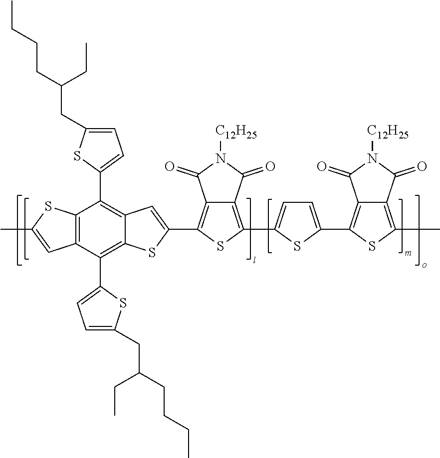
[0077]In order to synthesize a copolymer included in a photoactive material according to one embodiment of the present specification, the copolymer was formed by the following Reaction Formula 1.

[0078]Chlorobenzene (15 ml), 2,6-bis(trimethyltin)-4,8-bis(2-ethylhexyl-2-thienyl)-benzo[1,2-b:4,5-b′]dithiophene (0.7 g, 0.7738 mmol), 2,5-bis(trimethylstannyl)thiophene (0.3171 g, 0.7738 mmol), 1,3-dibromo-5-dodecylthieno[3,4-c]pyrrole-4,6-dione (0.7418 g, 1.548 mmol), tris(dibenzylideneacetone) dipalladium (0) (Pd2(dba)3, 28 mg), tri-(o-tolyl)phosphine (37 mg) were placed in a microwave reactor vial, and reacted for 1 hour under a 170° C. condition. The mixture was cooled to room temperature, methanol was poured thereinto, and then solids were filtered and then Soxhlet extracted using methanol, acetone, hexane and chloroform. The chloroform portion was precipitated again in methanol to filter solids.

example 2

[0079]In order to prepare a PEI solution, PEI and 1-butanol were mixed in a mass, ratio of 1:499, and stored for 24 hours or longer. A photoactive layer solution was prepared to have an approximately 3 wt % concentration employing a donor and an acceptor (CF, CB, ODCB or mixed solution of two or more thereof) in a 1:2 ratio.

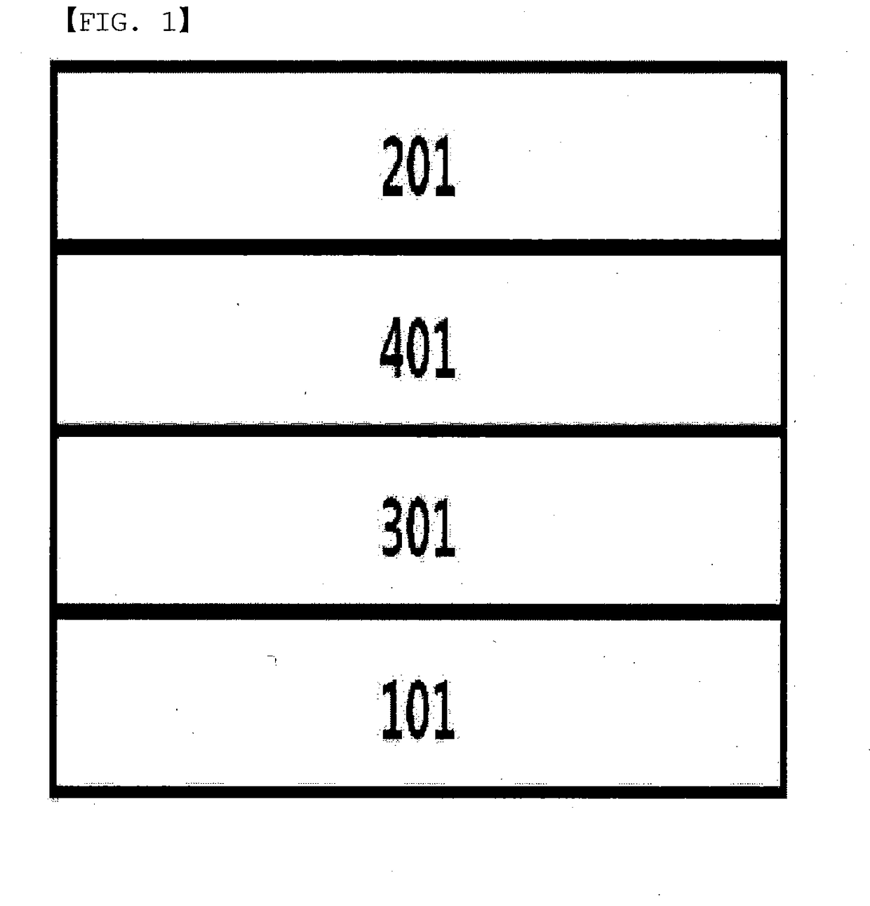
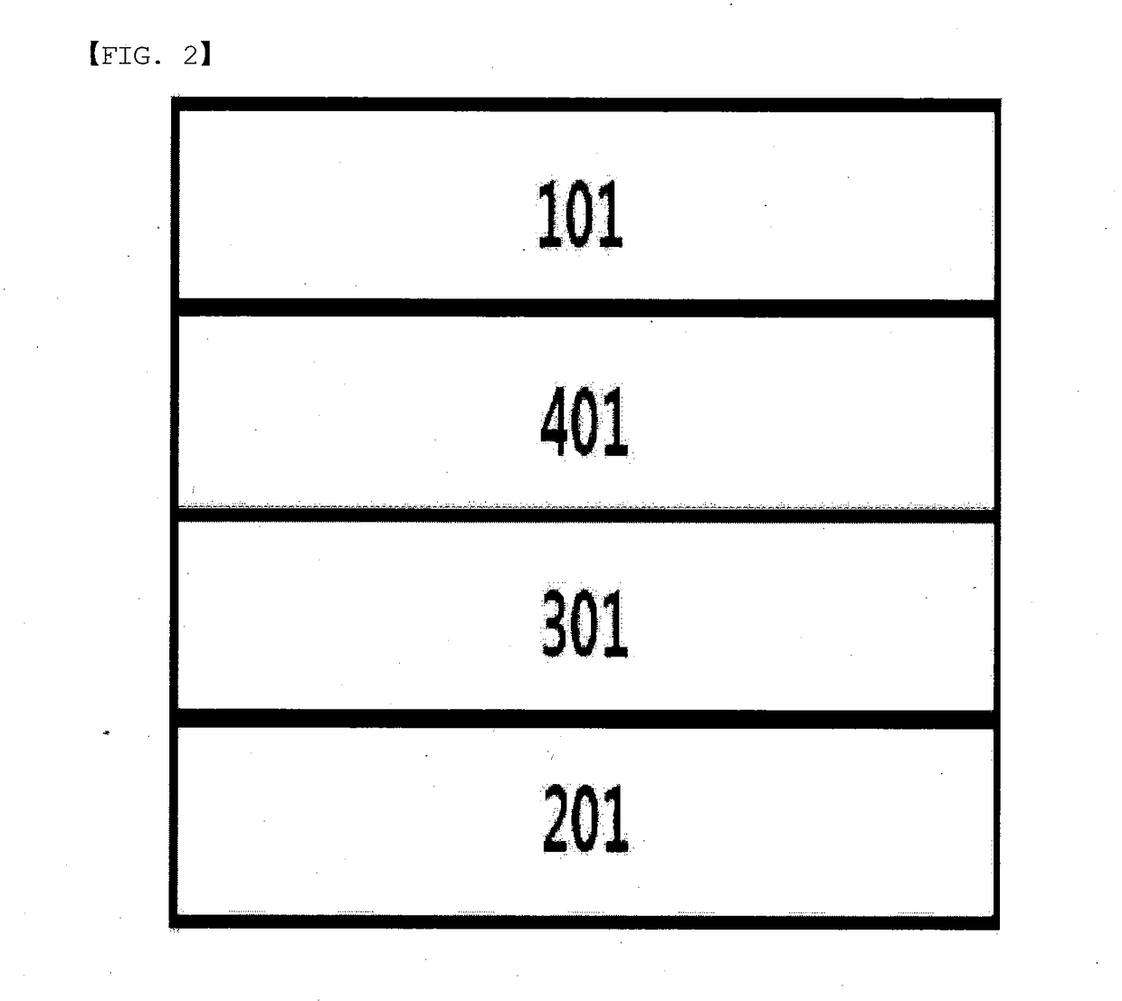
[0080]The photoactive layer solution according to one embodiment of the present specification was prepared by adding the PEI solution to the photoactive layer solution prepared above. In the structure (ITO / 125:PC61BM:PEI / MoO3 / Ag) prepared according to one embodiment of the present specification, 1,2,4-trichlorobenzene was included in 3% by weight, and a device was manufactured by coating while maintaining the temperature of the substrate and the temperature of the photoactive layer solution identically at 40° C.


PUM

PropertyMeasurementUnit
temperatureaaaaaaaaaa
densityaaaaaaaaaa
boiling pointaaaaaaaaaa

Abstract

The present specification provides an organic solar cell, and a method for manufacturing the same.

Description

TECHNICAL FIELD[0001]The present specification claims priority to and the benefits of Korean Patent Application No. 10-2016-0029651, filed with the Korean Intellectual Property Office on Mar. 11, 2016, the entire contents of which are incorporated herein by reference.[0002]The present specification relates to a method for manufacturing an organic solar cell, and an organic solar cell manufactured using the same.BACKGROUND ART[0003]According to an energy review material published by the NREL, a US National Laboratory, energy sources that are currently used mainly are petroleum, coal and gas. These energy sources amount to 80% of energy sources used in total. However, depletion of petroleum and coal energy has gradually become a big problem currently, and an increase in the emission of carbon dioxide and other greenhouse gases into the air is generating increasingly serious problems. In contrast, the use of renewable energy that is non-polluting green energy is yet about 2% of the tot...

Claims


Application Information

Patent Timeline
Patent Type & Authority Applications(United States)
IPC IPC(8): H01L51/00H01L51/44
CPCH01L51/0007H01L51/44H01L51/0043H01L51/0036H01L31/0256H10K71/15H10K85/113H10K85/151H10K30/80H10K30/30Y02E10/549
Inventor CHOI, DOOWHANLEE, JAECHOLKIM, JINSECKJANG, SONGRIMLEE, DONGGU
Owner LG CHEM LTD
Why Eureka
Try Eureka