
Electromagnetic induction type encoder

a type of encoder and induction current technology, applied in the direction of coils, instruments, measurement devices, etc., can solve the problems of insufficient intensity of intensive signals and attenuation of induction current generated, and achieve the effect of strong signal intensity reduction, high accuracy and inexpensiveness

Active Publication Date: 2011-03-15
MITUTOYO CORP
View PDF4 Cites 41 Cited by
  • Summary
  • Abstract
  • Description
  • Claims
  • Application Information

AI Technical Summary

Benefits of technology

The present invention provides an electromagnetic induction type encoder that is highly accurate, affordable, and durable against fluctuations in yaw direction. The invention solves the problem of offset reduction by using a short scale coil and a symmetrical positioning of the transmitting and receiving coils with respect to the scale. The receiving coils can be connected to each other to acquire a difference or sum of output between two receiving coils located at symmetrical positions around the center of the scale. The number of grid layers can be reduced, and the shape of the transmitting and receiving coils can be made common. The connection wiring of the scale coil can be omitted, and the shape of the scale coil can be made rectangular frame-like. The invention provides a small-sized, highly accurate, and durable encoder that is less error-prone and is durable against water and oil.

Problems solved by technology

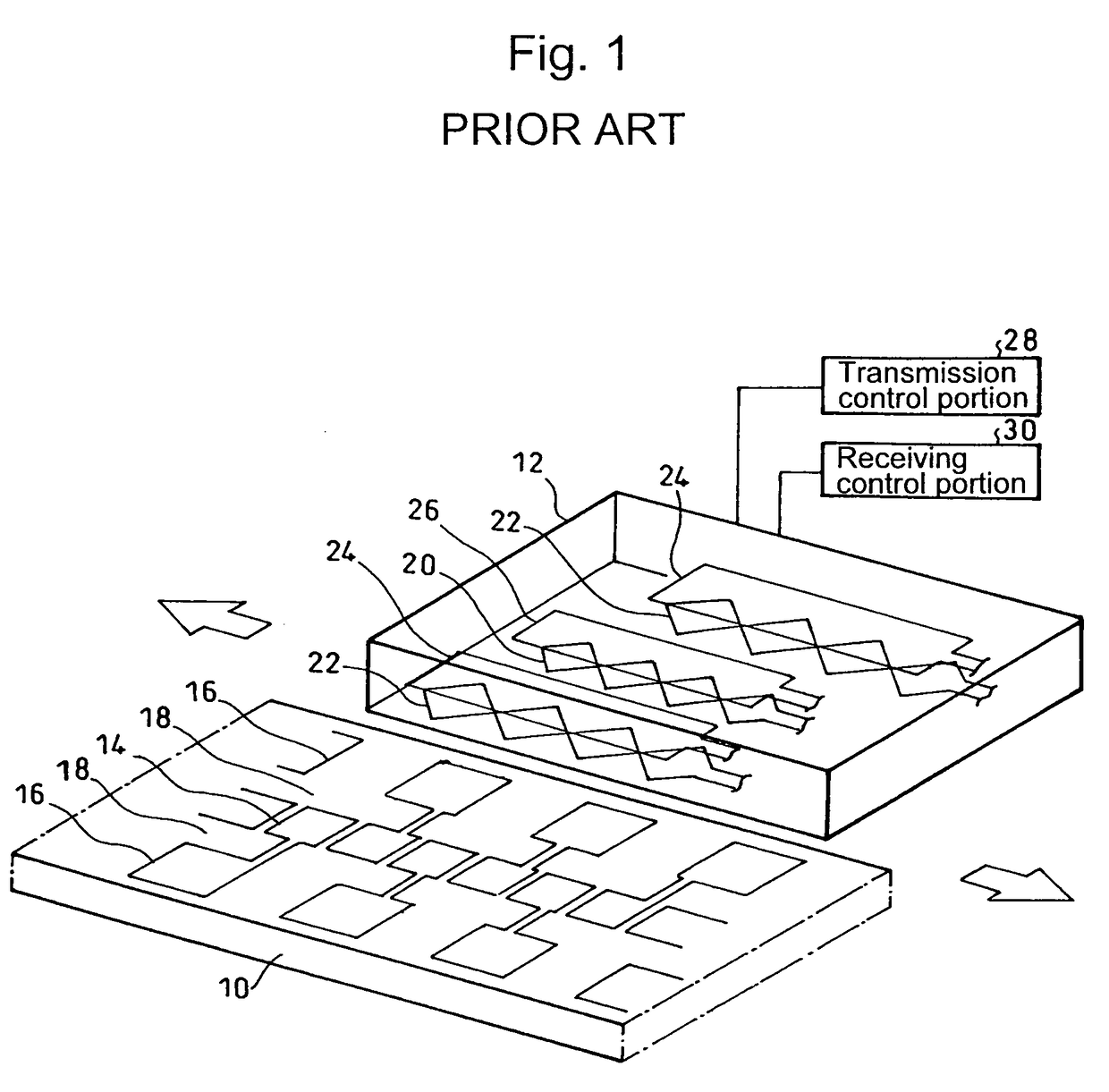
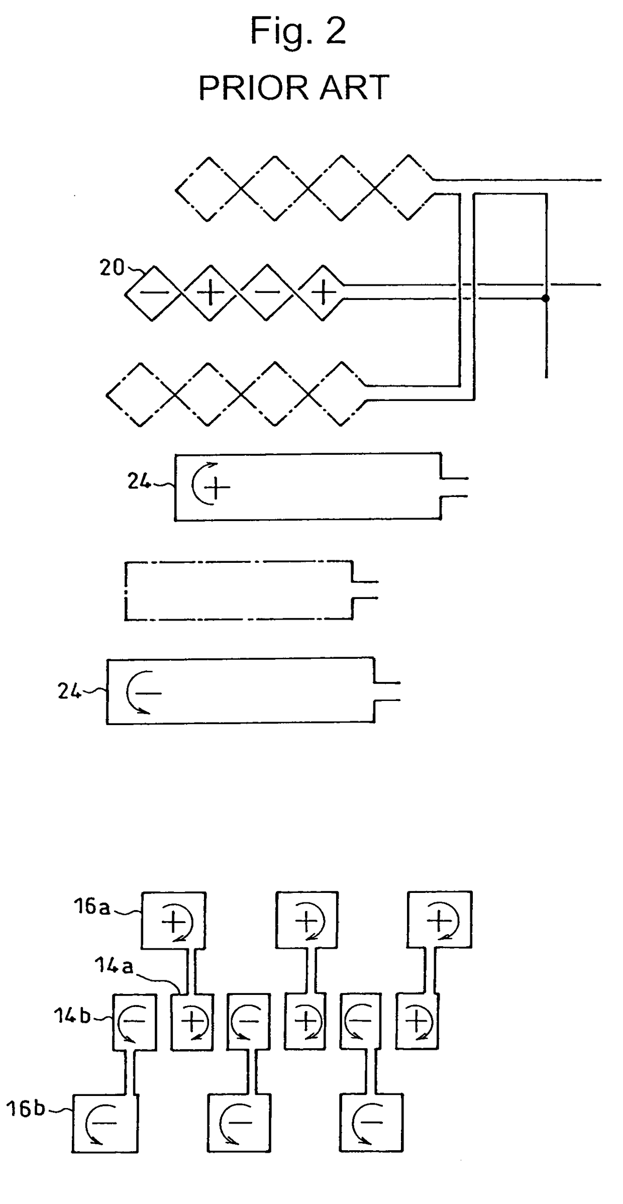
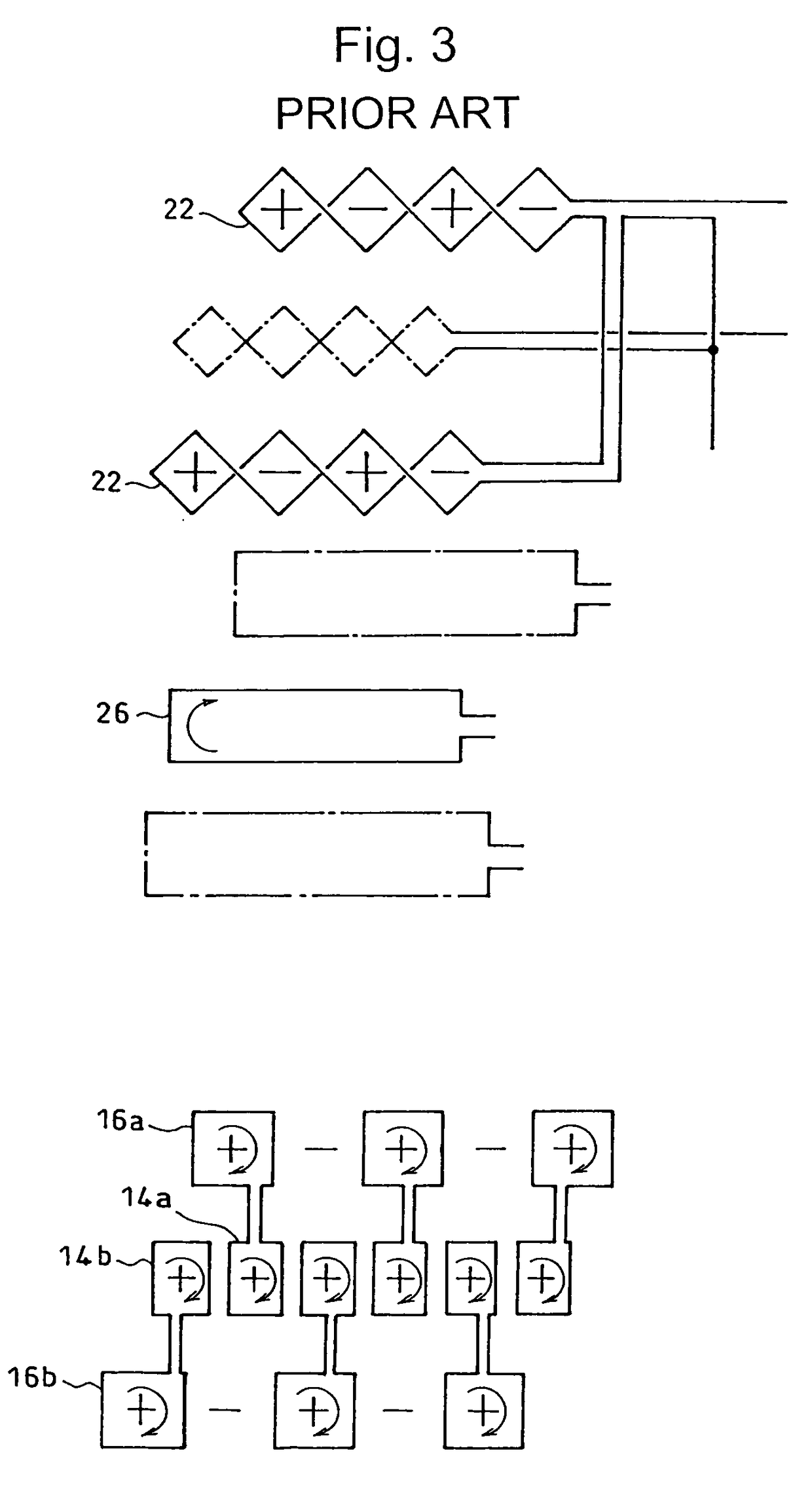
However, with the configuration, three rows of scale coils are required, wherein there arises a problem in that, since the wiring of the scale coils is lengthened, induction current generated attenuates due to impedance of the scale coil itself and intensive signals are hardly obtained.

Method used


Image

  • Electromagnetic induction type encoder
  • Electromagnetic induction type encoder
  • Electromagnetic induction type encoder

Examples


embodiment 1

[0034]As shown in FIG. 4, Embodiment 1 of the present invention is such that transmitting coils 24A, 24B and the receiving coils 20A, 20B on the same grid 12 and scale coils 14A, 14B on the scale 10 are disposed by two sets each symmetrically with respect to the center of the scale 10, and scale coil 14A of one set is shifted by ½ phase of the scale pitch (λ) with respect to scale coil 14B of the other set.

[0035]The shapes of two sets of transmitting coils 24A, 24B and the receiving coils 20A, 20B are made common to each other, and are connected so that an electric current flows to the transmitting coils 24A, 24B in the same direction and a difference in signals of the receiving coils 20A, 20B is output.

[0036]As shown by the arrows in FIG. 4, where an electric current flows to the two transmitting coils 24A, 24B in the same direction, magnetic fields are brought about at the transmitting coils 24A, 24B in the same direction. Here, since the phases of the scale coils 14A, 14B are shi...

embodiment 2

[0037]Next, a description is given of Embodiment 2 of the present invention. The present embodiment is such that, as shown in FIG. 6, an electric current flows to the transmitting coils 24A, 24B in the reverse direction, and the transmitting coils 24A, 24B and the receiving coils 20A, 20B are connected so as to output the sum of signals of the receiving coils 20A, 20B.

[0038]As in the present embodiment, where an electric current is caused to flow to the transmitting coils 24A, 24B in the opposite direction, magnetic fields are brought about in the opposite direction, respectively. At this time, as shown in FIGS. 7(A) and (B), a signal for which offset having different polarities is given on the same waveform is obtained in the receiving coils 20A, 20B. Therefore, by connecting the receiving coils 20A, 20B so that the signals of the two receiving coils 20A, 20B are added to each other, it is possible to obtain a signal for which the offset is cancelled, as shown in FIG. 7(C).

[0039]Al...


PUM


Abstract

The invention provides a highly accurate and inexpensive electromagnetic induction type encoder capable of acquiring strong signal intensity with the offset reduced by a short scale coil, and is durable against fluctuations in the yaw direction, which includes a number of scale coils 14 arrayed on a scale 10 along the measurement direction, and transmitting coils 24 and receiving coils 20 that are disposed on a grid 12 relatively movably in the measurement direction with respect to the scale, and which detects a relative movement amount of the scale and the grid from changes in magnetic fluxes detected by the receiving coils via the scale coil when the transmitting coils are magnetized, wherein a plurality of sets of the transmitting coils (24A, 24B), the receiving coils (20A, 20B) and the scale coils (14A, 14B) are disposed symmetrically with respect to the center of the scale, and scale coils of one set located at a symmetrical position around the center of the scale is disposed with ½ phase of the scale pitch shifted with respect to scale coils of the other set.

Description

CROSS-REFERENCE TO RELATED APPLICATION[0001]The disclosure of Japanese Patent Application No. 2008-23507 filed on Feb. 4, 2008 including specifications, drawings and claims is incorporated herein by reference in its entirety.BACKGROUND OF THE INVENTION[0002]1. Field of the Invention[0003]The present invention relates to an electromagnetic induction type encoder, and in particular to a highly accurate and inexpensive electromagnetic induction type encoder that is preferably used for calipers, indicators, linear encoders, micrometers, etc., and is capable of obtaining strong signal intensity with offset reduced by a short scale coil, and is durable against fluctuations in the yaw direction.[0004]2. Description of the Related Art[0005]As has been described in Japanese Published Unexamined Patent Application No. H10-318781 (hereinafter, referred to as Patent Document 1) and Japanese Published Unexamined Patent Application No. 2003-121206 (in particular, FIG. 1, FIG. 2, and FIG. 3) (here...

Claims


Application Information

Patent Timeline
Patent Type & Authority Patents(United States)
IPC IPC(8): G01B7/14
CPCG01D5/2073
Inventor NAKAYAMA, KENICHIKAWATOKO, OSAMUKUBOZONO, HIROTO
Owner MITUTOYO CORP
Learn More