
Surface inspection technology for the detection of porosity and surface imperfections on machined metal surfaces

Active Publication Date: 2005-10-06
BUDD GERALD W
View PDF8 Cites 27 Cited by
  • Summary
  • Abstract
  • Description
  • Claims
  • Application Information

AI Technical Summary

Benefits of technology

[0014] It is an object of the present invention to transform the present probabilistic detection of surface imperfections, namely porosity with an area equivalent to or larger than 0.400 μm diameter, into a deterministic detection and accurate measurement process.
[0018] It is a further object of the present invention to provide a method to uniformly illuminate substantially the entire surface of the component to be inspected.
[0019] It is a further object of the present invention to provide a method to control the intensity of the illumination source so provide accurate and repeatable measurements over an extended period of time (6-18 months between lamp replacements) in the production environment.
[0021] It is a further object of the present invention to provide a method for the generation of point cloud measurements for defects to aid in the identification of areas where the porosity levels have a higher level of incidence.

Problems solved by technology

The greater the amount of hydrogen in the molten aluminum and the slower it solidifies the greater the hydrogen voids will be.
This type of porosity is generally undetectable visually since the surface of the casting solidifies quickest preventing the hydrogen from forming holes large enough to be visible on the surface except by using fluorescent penetrant inspection.
However, after the removal of material from the surface of the casting by a machining operation the porosity generally becomes visible.
It is caused by a lack of adequate feed metal during solidification.
The inspection tasks can be very difficult because of complex inspection specifications written to handle the wide variation of porosity characteristics.
Any occurrence of porosity larger than a specified diameter (or dimension) constitutes a defective condition.
The occurrence of two or more smaller defects within a specified proximity to each other also constitutes a defective condition.
If more than a specified number of porosity defects appear on the entire component this constitutes as defective condition.
The number of conditions constituting a defective condition can be considered an overwhelming task of the human inspector and often results in acceptable product being rejected as “bad” or defective product being accepted as “good”.

Method used


Image

  • Surface inspection technology for the detection of porosity and surface imperfections on machined metal surfaces
  • Surface inspection technology for the detection of porosity and surface imperfections on machined metal surfaces
  • Surface inspection technology for the detection of porosity and surface imperfections on machined metal surfaces

Examples


Embodiment Construction

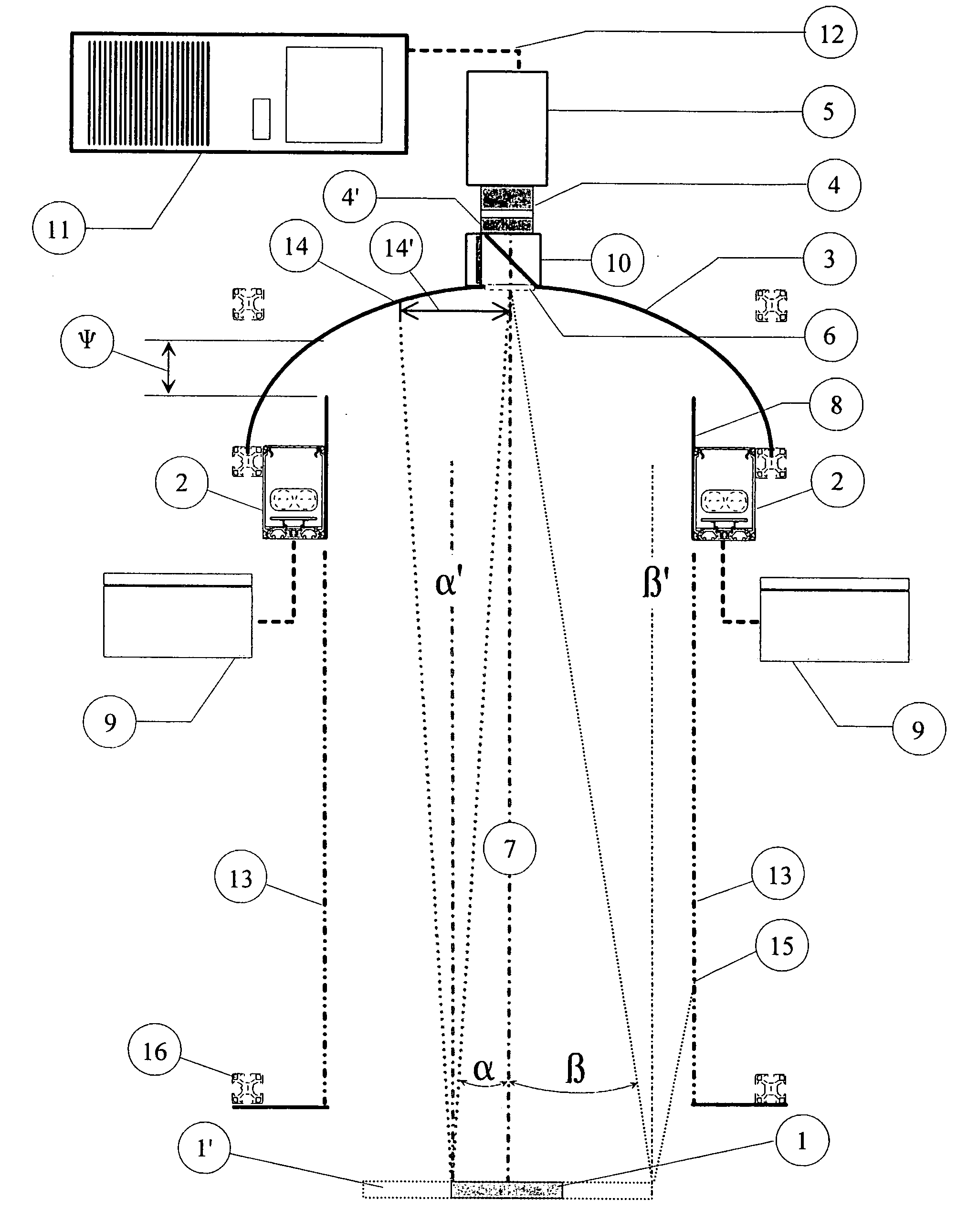
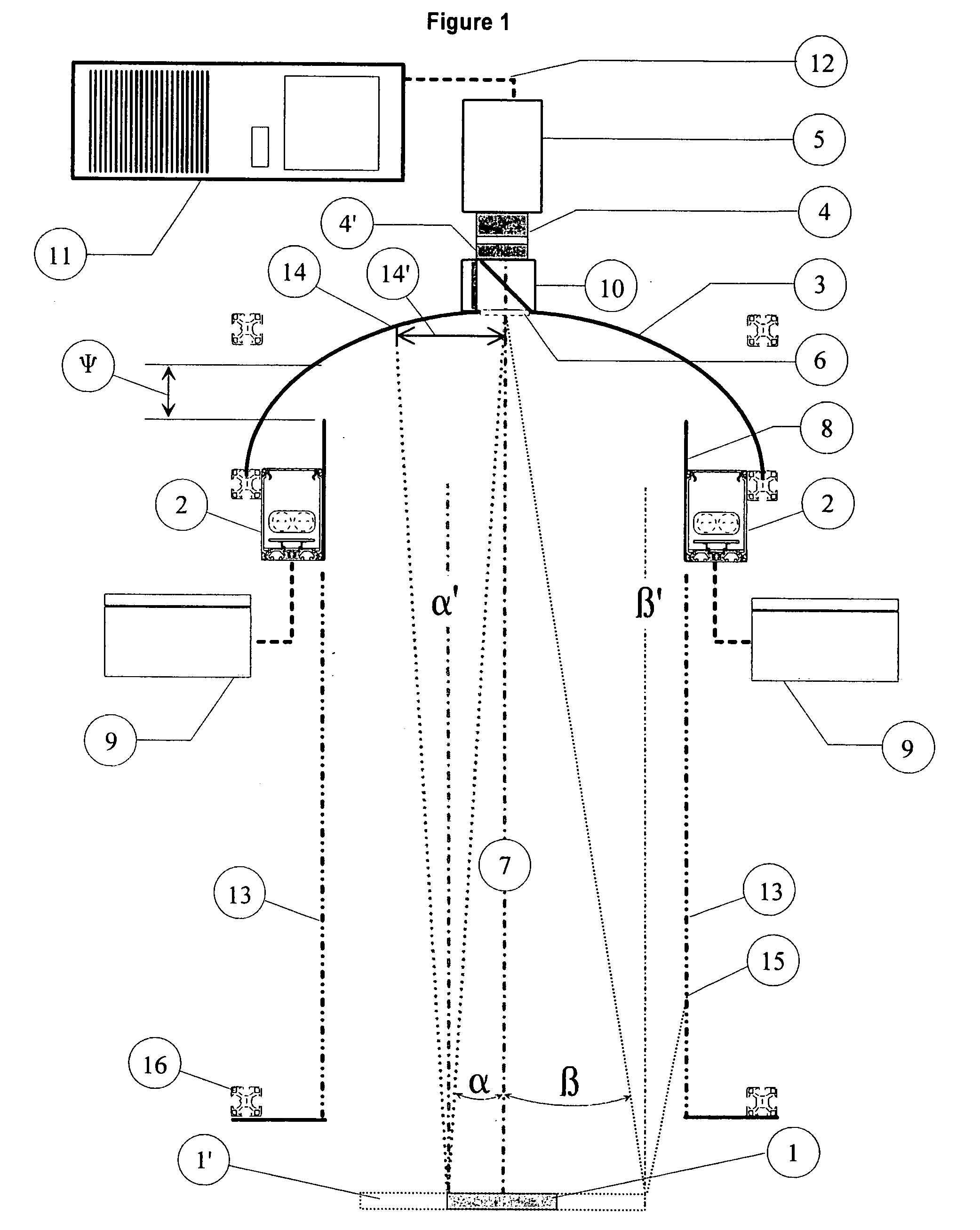
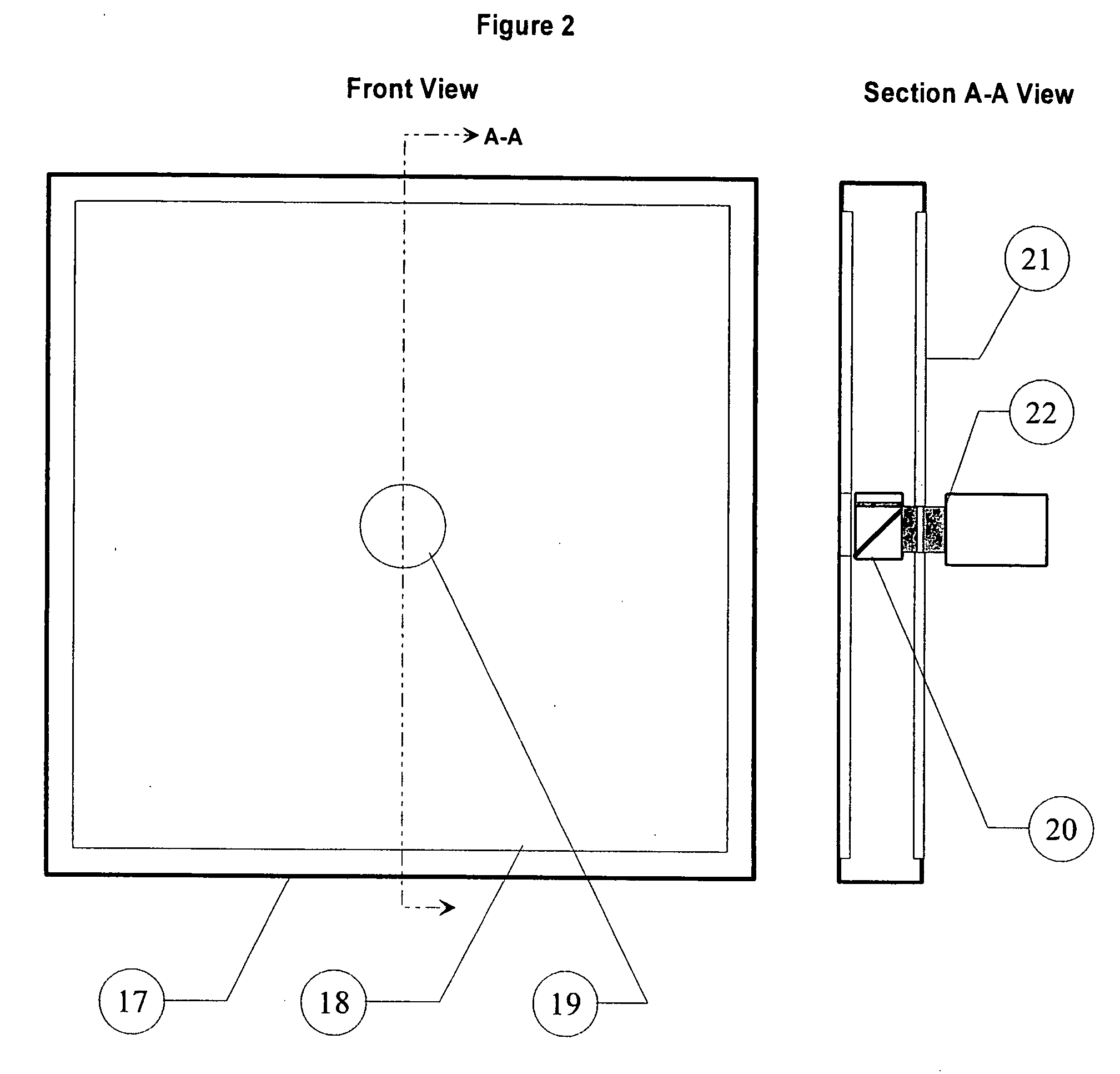
[0051] The present invention consists of several major components arranged in the proper configuration to produce image data that will yield repeatable measurements. The present invention, hereafter referred to as the “System” is comprised of several major components. The major components include 1) a mechanical device to aid in the location of the test components; 2) a high resolution image sensor (>3.2 mega-pixel); 3) a diffuse flat field illumination system with active-loop feedback control; 4) an image processor capable of supporting a minimum 65 MB of image memory; 5) specialized image processing software to extract surface imperfections; 6) special software to allow the communication of inspection parameters, data and results between devices; and 7) the necessary interface connections for the devices to exchange the data. The major components and their relationship to each other in the system are illustrated in FIG. 1. The system design allows it to inspect large surfaces usin...


PUM


Abstract

A method for the substantially complete detection and measurement of all surface imperfections, within a predetermined size range, contained on the surface of a machined metal component comprising the steps of: a) the accurate positioning of a sample so to expose substantially all of the surface imperfections to be viewed by a high resolution sensor; b) uniformly illuminating the surface of the sample with light; and c) detecting at least one of light scatter, light reflection and light extinction caused by said surface imperfections, with detectors having a depth of focus and field of view of detection over the entire visible surface of the sample. Wherein the detectors are positioned, relative to the sample whereby the optical path and field of view allows the sensor sufficient focus to view substantially all of the samples' surface. The method and apparatus produces a geometric representation of the surface imperfections in the detection region, whereby the size of detected imperfections can be is accurately adjusted to an actual size by either calculation or by calculated offset to allow accurate dimensional measurement of the imperfections.

Description

CROSS-REFERENCE TO RELATED APPLICATIONS [0001] I claim priority to my Provisional Patent Application No. 60 / 557,490 with filing date Mar. 30, 2004.FIELD OF THE INVENTION [0002] This invention relates to the procedures and devices utilized in the optical inspection of metal and non-metal components for the presence of surface imperfection and particularly to inspection of porosity on machined aluminum castings. BACKGROUND OF THE INVENTION [0003] The author of this invention has worked in the field of machine vision inspection for over 15 years. There have been many advancements in the field of machine vision during the past ten years, in particular the speed at which the image processing algorithms can process the information. There have also been advances in the resolution of the sensor (CCD and CMOS) used to acquire the images of objects under inspection. Industry, in particular the aerospace and automotive industries have long desired a robust method for the detection of surface p...

Claims


Application Information

Patent Timeline
IPC IPC(8): G01N21/88G06K9/00
CPCG01N2021/8812G01N21/8851
Inventor BUDD, GERALD W.
Owner BUDD GERALD W
Learn More