Robot for training a rehabilitator

Active Publication Date: 2008-11-20
OKI ELECTRIC IND CO LTD
View PDF22 Cites 31 Cited by
  • Summary
  • Abstract
  • Description
  • Claims
  • Application Information

AI Technical Summary

Benefits of technology

[0011]A further aspect of a robot for training a rehabilitator according to the present invention comprises a spring element for a bi-articular muscle interconnecting the first and second joints, as an inner model. The rotational angles of the first and second actuators when the rehabilitator has exerted the force to the distal end of the first link in an optional direction are detected. The rotational angles are converted into torques acting on the first and second actuators based on the inner model. The driving voltage or the driving current necessary to generate the torques is applied to the first and second actuators to virtually reproduce the torques by the spring element of the bi-articular muscle to permit the rehabilitator to physically experience the torques.
[0012]With a still further aspect of a robot for training a rehabilitator according to the present invention, the bi-articular arm device includes a skin unit covering up the surfaces of the first and second links and a light

Problems solved by technology

The conventional robot thus cannot accurately define the characteristics of, e.g. three paired muscles, totaling at six muscles, with

Method used


Image

  • Robot for training a rehabilitator
  • Robot for training a rehabilitator
  • Robot for training a rehabilitator

Examples


first embodiment

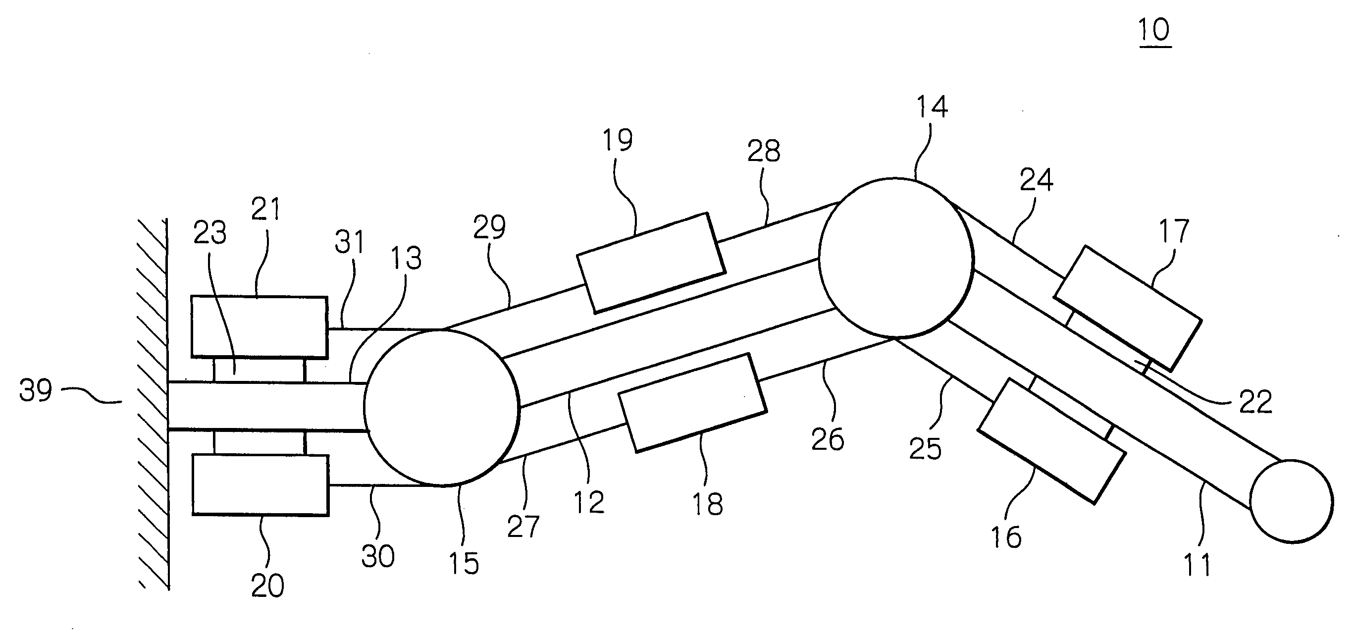
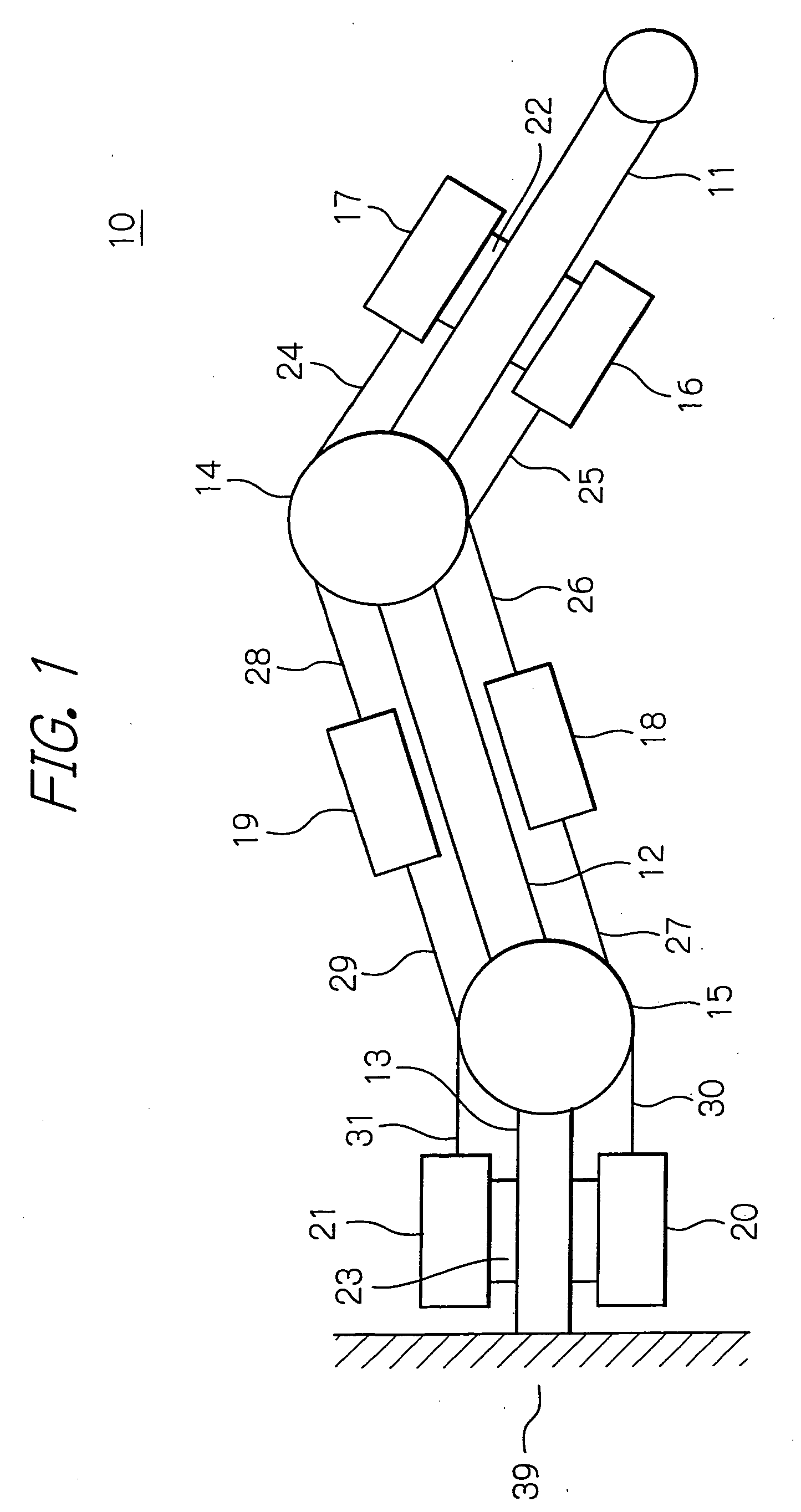
[0041]In FIG. 1, a bi-articular arm device 10 is included in a robot for training a trainer in rehabilitation exercise, or a rehabilitator, and has a structure simulating the lower limb, that is, a leg, of the human body. The bi-articular arm device 10 may alternatively be of a structure that simulates the upper limb, that is, an arm, of the human body. The following description will, however, focus on the bi-articular arm device 10 having its structure simulating the lower limb of the human body.

[0042]The bi-articular arm device 10 has a first link 11 that simulates the lower limb is for the lower thigh, and a second link 12 that simulates the lower limb is for the upper thigh. A frame 13, as a base, is for the waist part, and has a proximal part (left-hand end in FIG. 1) secured to a stationary member 39, secured in turn to, for example, a foundation, not shown. To the distal end (right-hand end in FIG. 1) of the frame 13 is rotatabley connected the proximal end of the second lin...

third embodiment

[0125]Since the constitution of the robot for training a rehabilitator is similar to that of the above-described third embodiment, a repetitive description thereof will be dispensed with.

[0126]The control block diagram of the bi-articular arm device 100 for the present embodiment is shown in FIG. 22. In this figure, a transfer function 110 for the first motor 68 includes inertial moments about the first link 65 and the second link 64. In similar manner, a transfer function 101 for the second motor 69 includes the inertial moment about the first link 65.

[0127]The reference numerals 102, 103 denote controllers for causing voltages corresponding to the target torque values T1ref and T2ref to be applied to the transfer functions 110, 101, as controlled objects, respectively. The reference numerals 106, 107 each denote a transfer function including the spring element K and a distance (radius) R from the center of rotation of the joint up to a point on which acts the spring, as shown in F...

second embodiment

[0139]Referring to FIG. 25, the controller of the present embodiment may be the controller of the second embodiment shown in FIG. 16 in which there are additionally provided light emitting driving circuits 130 to 135, as drivers for the light emitting sections 122 to 127. Meanwhile, the light emitting sections 122 to 127 are here assumed to be light emitting diodes.

[0140]The light emitting driving circuits 130 to 135 are connected to the light emitting sections 122 to 127, respectively, and turn the light emitting sections 122 to 127 on or off under the instructions from the central processor unit 150.

[0141]The controller of the present embodiment may also be the controller of the first embodiment of FIG. 5 in which there are additionally provided the light emitting driving circuits 130 to 135.

[0142]The operation of the bi-articular arm device 210 of the present embodiment will now be described. For optionally setting the actuator(s), which are to be in operation, as in the above-de...


PUM


Abstract

In a robot for training a rehabilitator, the driving of actuators is controlled to generate the forces acting in six directions at the distal end of a bi-articular arm device to reproduce the relationship between the muscular output of the upper or lower limb of the human body and the output direction at the distal end of the limb. The rehabilitator can experience the relationship between the outputs of his or her limb muscles and the output direction at the distal end of the limb. Thus, the six actuators are run in operation along a predetermined sequence. One or more of the actuators, selected so that the direction of the force generated at the distal end of the first link will be the selected direction, is run in operation. The rehabilitator holding the distal end of the first link may physically experience the direction of that force.

Description

BACKGROUND OF THE INVENTION[0001]1. Field of the Invention[0002]The present invention relates to a robot or machine for training a rehabilitator.[0003]2. Description of the Background Art[0004]There has been proposed a robot or machine for training a rehabilitator, such as a physical therapist involved in rehabilitation, e.g. resistance training for restoring physical functions of aged persons or persons rallied from their illness or injury. See, for example, Japanese patent laid-open publication No. 2006-204832.[0005]In the conventional robot for training a rehabilitator, however, the muscular output of hip and knee joints is simulated solely by the torques at the respective joints. The conventional robot thus cannot accurately define the characteristics of, e.g. three paired muscles, totaling at six muscles, with the result that a trainer in rehabilitation exercise, or a rehabilitator, is unable to properly experience the output of each muscle.SUMMARY OF THE INVENTION[0006]It is a...

Claims


Application Information

Patent Timeline
IPC IPC(8): B25J13/00
CPCA61H1/0237A61H1/0274B25J9/046B25J9/104G09B9/00G09B19/003A61H2201/14A61H1/0262A61H2201/1215A61H2201/1676
Inventor TOKITA, MAMORUSHIMADA, KOUKICHI
Owner OKI ELECTRIC IND CO LTD
Why Eureka
Try Eureka