Lenticular Autostereoscopic Display Device and Method, and Associated Autostereoscopic Image Synthesising Method

a display device and autostereoscopic technology, applied in the field of lenticular autostereoscopic display devices and methods, and associated autostereoscopic image synthesising methods, can solve the problems of lenticular color autostereoscopic screens with a loss problem based on horizontal resolution, more expensive manufacture and use, etc., to achieve the effect of equalizing the loss of resolution

Inactive Publication Date: 2008-11-27
ARTISTIC IMAGES
View PDF11 Cites 15 Cited by
  • Summary
  • Abstract
  • Description
  • Claims
  • Application Information

AI Technical Summary

Benefits of technology

[0017]With a display device according to one embodiment, it becomes possible to equalize the loss of resolution in the two horizontal and vertical dimensions of the screen. Thus, for 4 viewpoints, the loss of resolution, with a factor of 2, is the same horizontally and vertically. For higher numbers of viewpoin

Problems solved by technology

Parallax barriers are easy to implement, and inexpensive to produce, but constitute an impediment, having too much photon loss, especially when it is desired to encode numerous angles of view.
This results in problems relating to the photon flux and brightness of the screen.
Autostereoscopic screens that implement lenticular arrays have very few photon losses and therefore have a transmission rate close to 100%, but are more costly to manufacture and more difficult to use.
Current lenticular color autostereoscopic screens have a horizontal resolution loss problem based on the number of viewpoints.
Thus, a problem posed is to find an appropriate way to encode the P views on the 2 D electronic screen in order to equalize the horizontal and ver

Method used


Image

  • Lenticular Autostereoscopic Display Device and Method, and Associated Autostereoscopic Image Synthesising Method
  • Lenticular Autostereoscopic Display Device and Method, and Associated Autostereoscopic Image Synthesising Method
  • Lenticular Autostereoscopic Display Device and Method, and Associated Autostereoscopic Image Synthesising Method

Examples


Embodiment Construction

[0037]An exemplary autostereoscopic display device according to one embodiment of the invention will first be described with reference to FIGS. 2A to 2D.

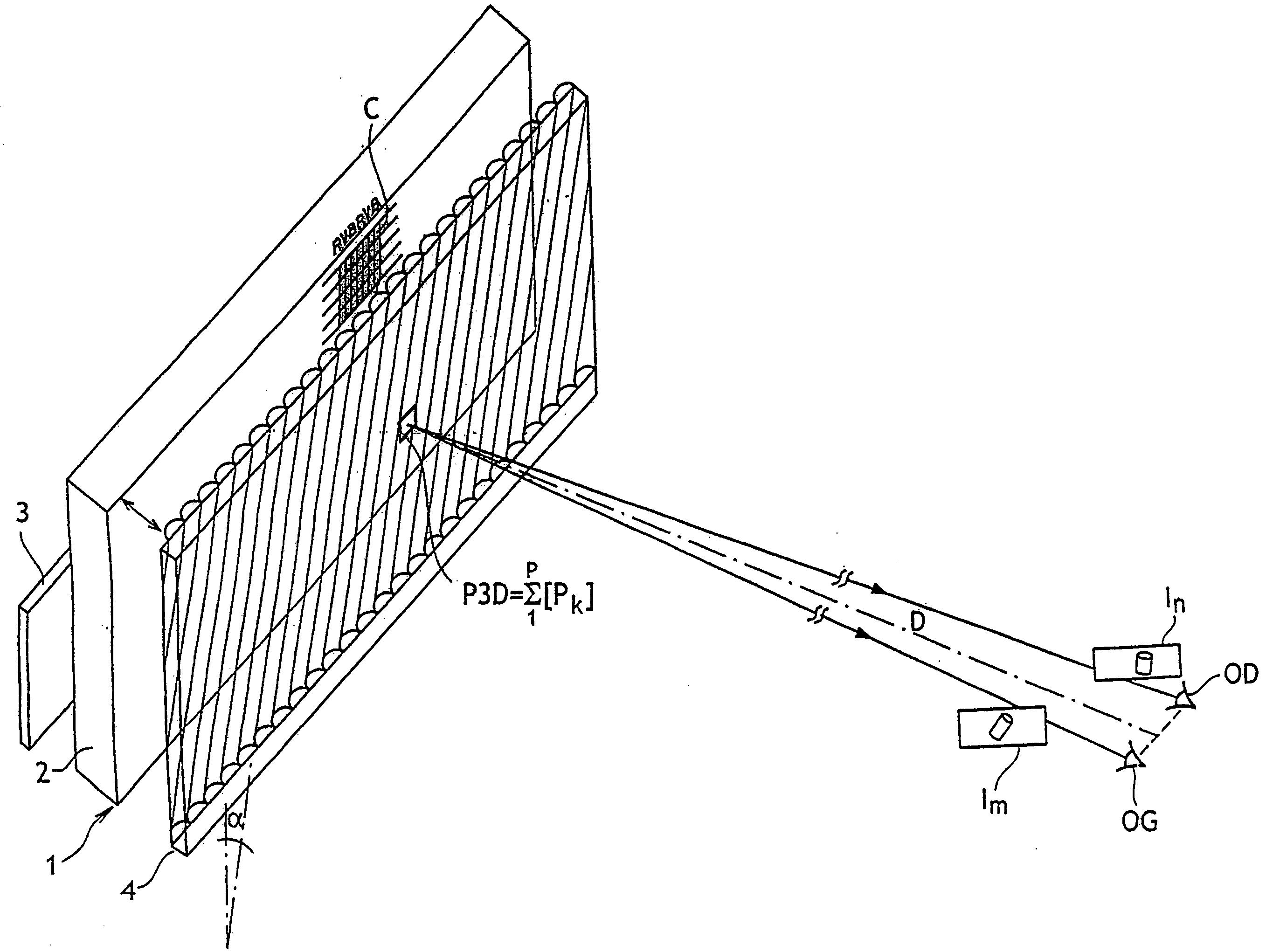
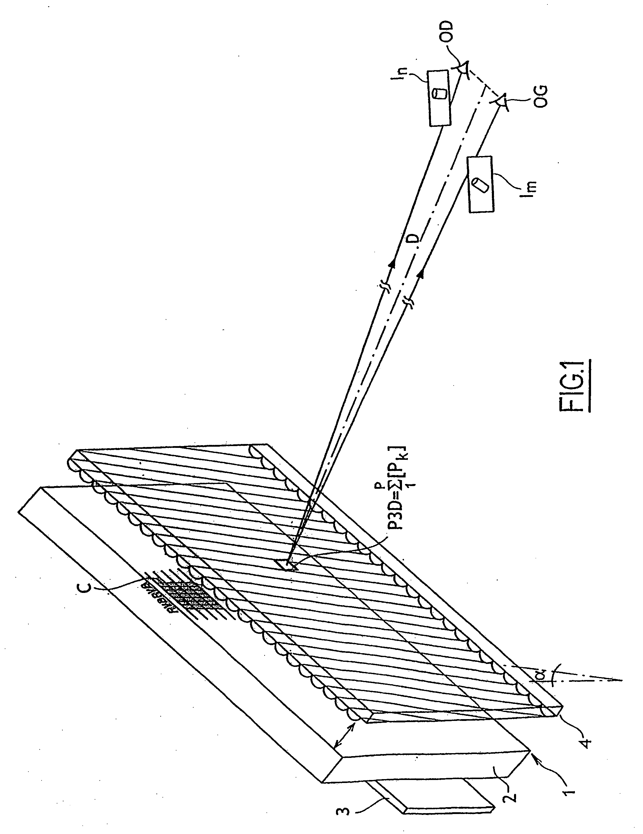
[0038]The autostereoscopic display device 1 includes a plasma screen 2 connected to an electronic module 3 for generating encoded images, and a lenticular filter 4 in the form of an array of parallel cylindrical lenses inclined at an angle a in relation to the vertical axis of the plasma screen, this lenticular filter 4 being arranged in front of the plasma screen at a distance substantially equal to the focal length F1 of the lenses, which in an actual exemplary embodiment is 9 mm, while each color cell of the display screen has a width of 286 μm.

[0039]The autostereoscopic display device 1 according to—this embodiment is anticipated to provide a display of advertising or informational messages at a sufficiently large distance D from the screen, e.g., at a distance greater than 2 m, whereby each eye OG OD of a viewer receives separa...


PUM


Abstract

An autostereoscopic display device includes a matrix display screen and a lenticular array arranged in front of the display screen. The lenticular array is adapted to receive and optically process a raster image transmitted by the display screen, with the raster image being encoded in order to integrate a plurality P of viewpoints of a same scene. The display screen includes a matrix of screen pixels, each of which includes three color cells organized in rows and columns laid out so as to form columns of a same color within the screen. The image transmitted by the display screen comprises a set of three-dimensional pixels, each integrating the plurality P of viewpoints of an image pixel of the scene, and each three-dimensional pixel occupying 3×P color cells in two adjacent rows within the screen.

Description

RELATED APPLICATIONS[0001]This application claims priority to PCT Application No. PCT / FR2005 / 0002562 filed Oct. 14, 2005, and French Application No. 0411018 filed Oct. 18, 2004, the disclosures of which are hereby incorporated by reference in their entireties.TECHNICAL FIELD[0002]This invention relates to a lenticular autostereoscopic display device. It also concerns an autostereoscopic display method implemented in this device, as well as an associated autostereoscopic image synthesizing method. The field of the invention is more particularly that of three-dimensional color computer and television screens intended, for example, for broadcasting advertising or public information messages or for displaying educational or entertainment content.BACKGROUND ART[0003]Glasses-free autostereoscopic display devices are already known, which implement either parallax barrier technologies or lenticular technologies. Overall, an autostereoscopic display screen includes:[0004]a plasma or liquid c...

Claims


Application Information

Patent Timeline
IPC IPC(8): H04N13/04G02B30/27
CPCG02B27/2214H04N13/0404H04N13/0415H04N13/0422H04N13/305H04N13/324H04N13/317G02B30/27H04N13/00G02B30/00
Inventor LEVECO, XAVIERAZOULAY, ARMAND
Owner ARTISTIC IMAGES
Why Eureka
Try Eureka