
Non-bracket windshield wiper

Active Publication Date: 2008-12-04
LIN SALLY
View PDF6 Cites 30 Cited by
  • Summary
  • Abstract
  • Description
  • Claims
  • Application Information

AI Technical Summary

Benefits of technology

[0005]The present invention has been accomplished under the circumstances in view. It is one object of the present invention to provide a non-bracket windshield wiper which saves much material cost and is easy to assemble without rivets. It is another object of the present invention to provide a non-bracket windshield wiper which allows free replacement of the rubber blades. To achieve these and other objects of the present invention, the non-bracket windshield wiper comprises an H-shaped and smoothly arched elastic metal bow strip, which has a middle neck and two longitudinal crevices at two sides of the neck, a holder frame mounted with a packing member and affixed to the middle part of the elastic metal bow strip for mounting to a windshield, two holding strips respectively coupled to the longitudinal crevices of the elastic metal bow strip, two back rubber strips respectively coupled to two top engagement structures of the holding strips, a rubber wiper blade coupled to two bottom engagement structures of the holding strips, and two end caps respectively capped on the two ends of the elastic metal bow strip.

Problems solved by technology

This design of windshield wiper has a complicated structure formed of multiple component parts.
The fabrication and assembly process of this design of windshield wiper are complicated, resulting in a high manufacturing cost.

Method used


Image

  • Non-bracket windshield wiper
  • Non-bracket windshield wiper
  • Non-bracket windshield wiper

Examples


Embodiment Construction

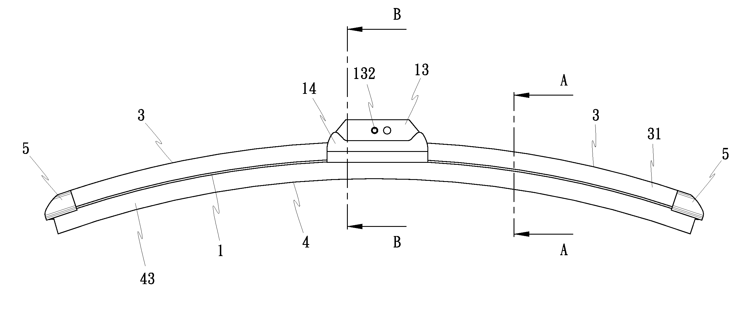
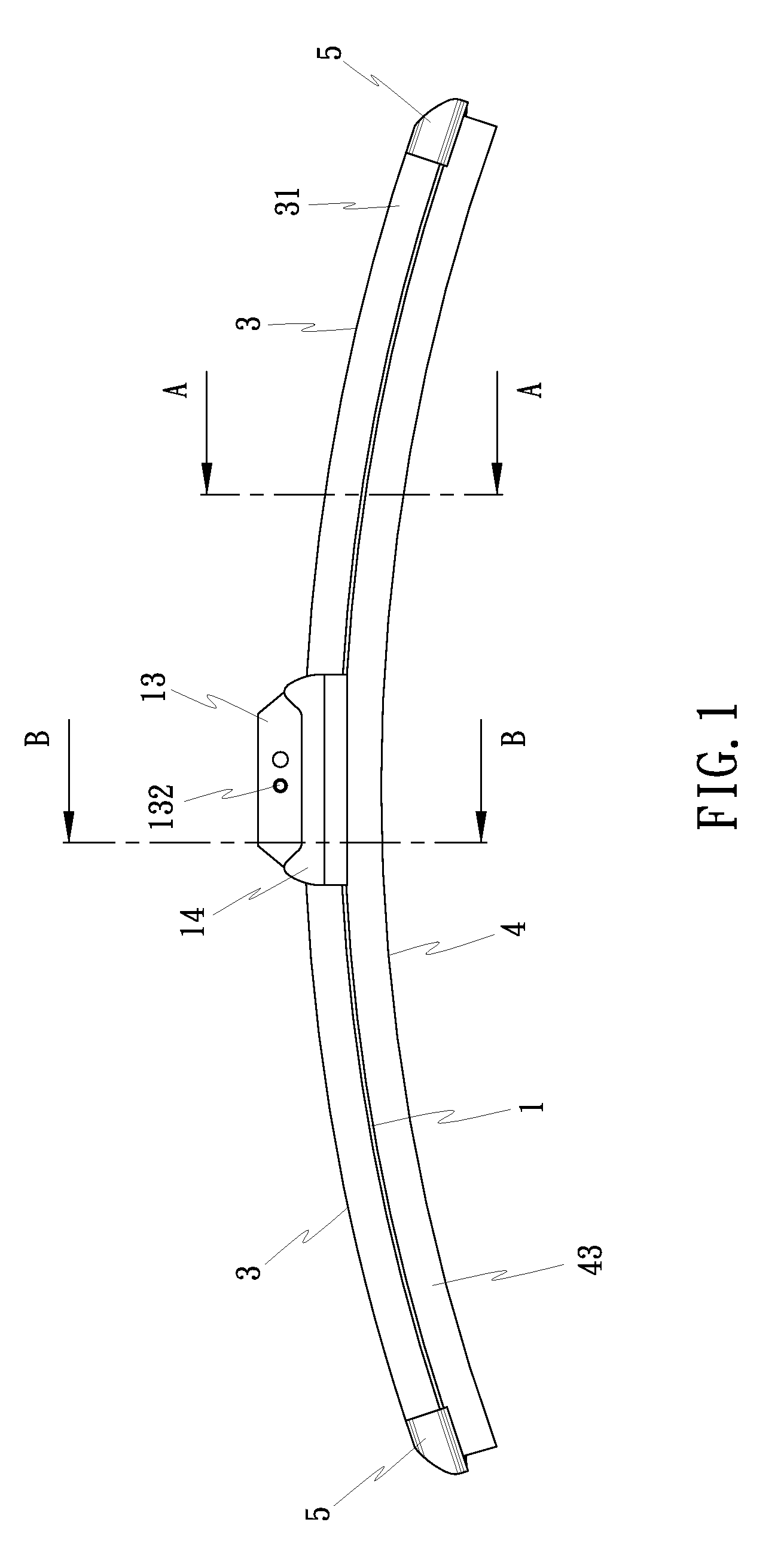
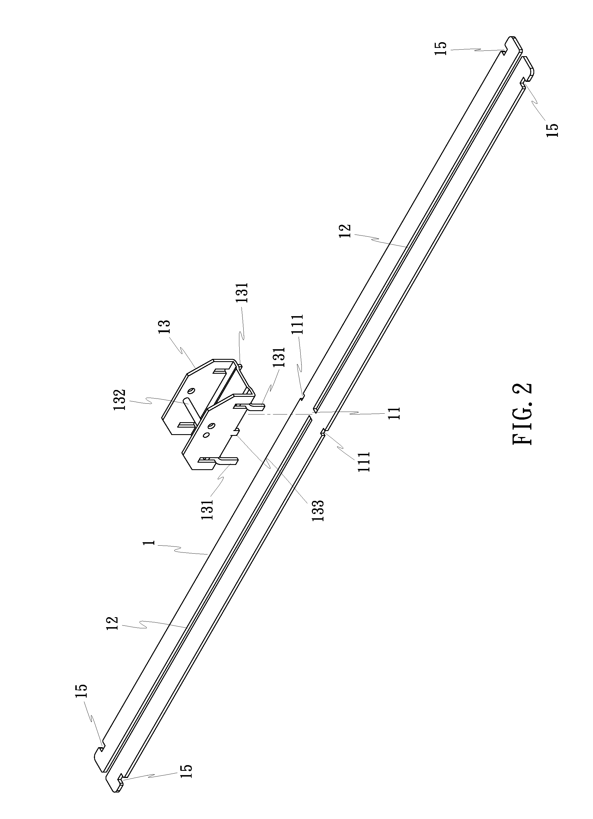
[0013]Referring to FIGS. 1˜3, a non-bracket windshield wiper in accordance with the present invention comprises a elastic metal bow strip 1, two holding strips 2, two back rubber strips 3, a rubber wiper blade 4, and two end caps 5.

[0014]The elastic metal bow strip 1 has a neck 11 on the middle, two elongated crevices 12 longitudinally aligned at two sides of the neck 11 (see FIG. 2), two retaining notches 111 on the two opposite lateral side edges thereof corresponding to the neck 11, for the mounting of a holder frame 13, which is mounted with a rubber packing member 14 (see FIG. 3). FIGS. 2 and 3 show the elastic metal bow strip 1 straightly extended out. Before application, the elastic metal bow strip 1 is stamped into a smoothly arched shape (see FIG. 1). Further, the elastic metal bow strip 1 has a hook notch 15 at each of the two opposite sides of the two opposite ends.

[0015]The two holding strips 2, as shown in FIG. 3 and FIG. 4, are preferably made of a flexible plastic mat...


PUM


Abstract

A non-bracket windshield wiper includes an H-shaped and smoothly arched elastic metal bow strip having a middle neck and two longitudinal crevices at two sides of the neck, a holder frame mounted with a packing member and riveted to the middle part of the elastic metal bow strip for mounting to a windshield, two holding strips respectively coupled to the longitudinal crevices of the elastic metal bow strip, two back rubber strips respectively coupled to two top engagement structures of the holding strips, a rubber wiper blade coupled to two bottom engagement structures of the holding strips, and two end caps respectively capped on the two ends of the elastic metal bow strip.

Description

BACKGROUND OF THE INVENTION[0001](a) Field of the Invention[0002]The present invention relates to a windshield wiper and more particularly to a non-bracket windshield wiper.[0003](b) Description of the Prior Art[0004]A conventional windshield wiper for automobile, as shown in FIG. 7, is comprised of a bracket structure holding a rubber blade 10. The bracket structure comprises an arm holder frame 201, two arms 202 respectively riveted to the two distal ends of the arm holder frame 201 with a respective rivet 402, and two extension strips 203 respectively riveted to the distal ends of the arms 202 with a respective rivet 402 to hold the rubber blades 10. Further, a pivot shaft 301 is transversely riveted to the arm holder frame 201 on the middle for mounting to a windshield. This design of windshield wiper has a complicated structure formed of multiple component parts. The fabrication and assembly process of this design of windshield wiper are complicated, resulting in a high manufac...

Claims


Application Information

Patent Timeline
IPC IPC(8): B60S1/32
CPCB60S1/381B60S1/3848B60S1/3856B60S1/3867B60S1/3881B60S1/40B60S2001/3817
Inventor LIN, SALLYKU, YUAN-CHIN
Owner LIN SALLY
Learn More