

Electrical connector
- Summary
- Abstract
- Description
- Claims
- Application Information
AI Technical Summary
Benefits of technology
Problems solved by technology
Method used
Image

Examples
first embodiment
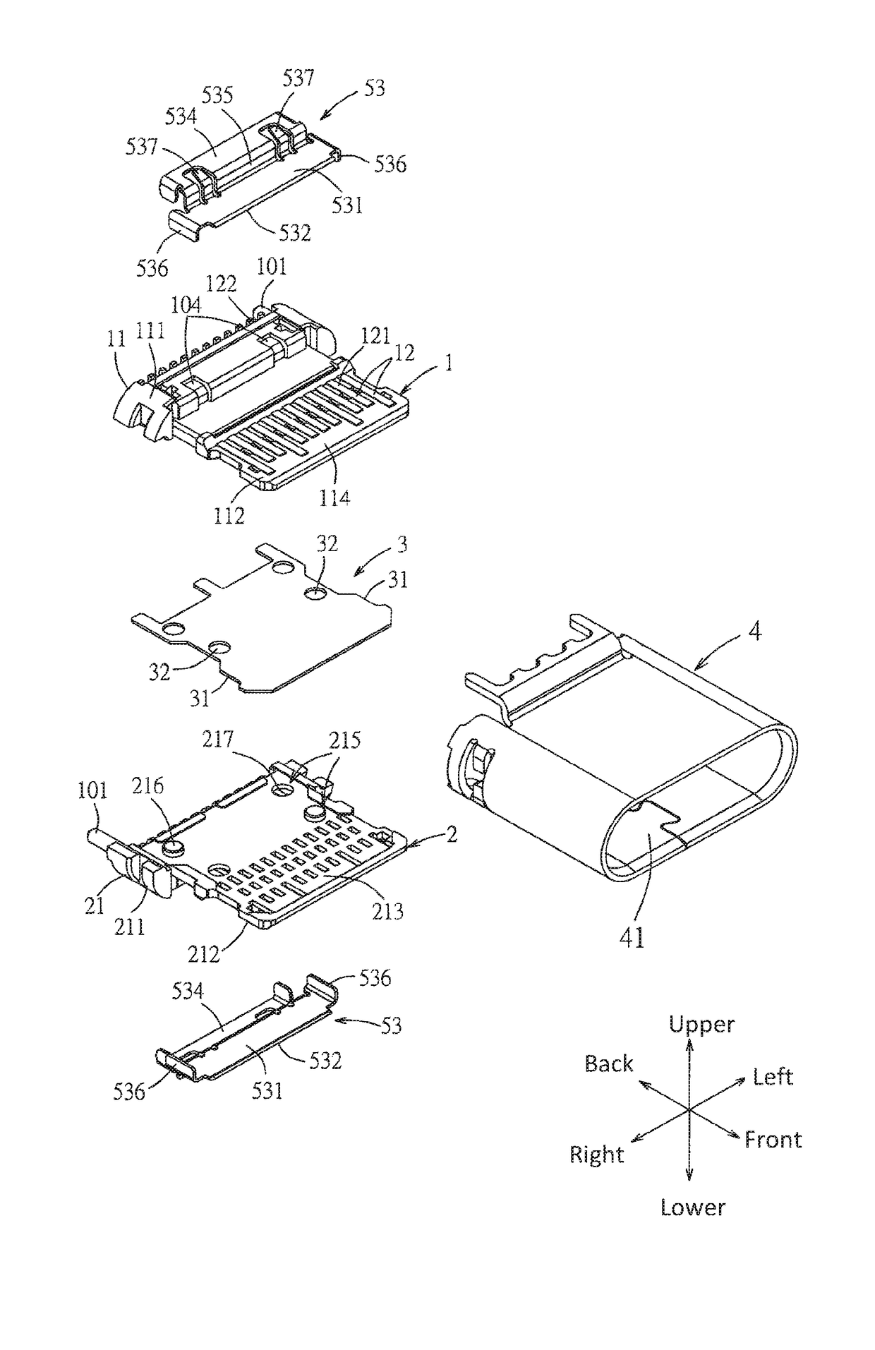
[0058]The grounding metal plate 3 is interposed between the first terminal module 1 and the second terminal module 2, thereby increasing the strength of the configuration of a tongue assembled by the first tongue portion 112 and the second tongue portion 212 and decreasing the crosstalk of high frequency signals between the first terminal 12 and the second terminal 22. Two opposite surfaces of the grounding metal plate 3 respectively attach on the first combined surface 113 of the first tongue portion 112 and the second combined surface 213 of the second tongue portion 212, the grounding metal plate 3 is provided with two mating side edges 31 exposed out of the first tongue portion 112 and the second tongue portion 212 respectively at a left side and a right side and four through holes 32 vertically penetrating the grounding metal plate 3. The four through holes 32 correspond to the two first fixing mechanisms 115 of the first insulative piece 11 and the two second fixing mechanisms...
second embodiment
[0064]Referring to FIG. 10 to FIG. 24, the electrical connector of the present disclosure is provided. The electrical connector 300c is a right angle connector.
[0065]Referring to FIG. 10 and FIG. 11, the electrical connector 300c may be provided to a circuit board 8c for matting of a mating connector 7c.
[0066]Referring to FIG. 11 to FIG. 17, the electrical connector 300c comprises an insulative body 10c, a plurality of terminals 20c, an outer shielding shell 4c, an inner shielding shell 5c, a grounding metal plate 3c and a soldering leg positioning member 6c.
[0067]The insulative body 10c is assembled by a first insulative piece 11c and a second insulative piece 21c, and has a main body 13c and a tongue 14c protruding forwards from the main body 13c. The main body 13c has a wider upper surface 131c, a wider lower surface 132c, two side surfaces 133c and a front surface 134c connecting the upper surface 131c and the lower surface 132c. The tongue 14c has a base portion 141c connecte...
PUM
 Abstract
Description
Claims
Application Information