
Backlight modules nad display panels

a backlight module and display panel technology, applied in the field of liquid crystal display technology, can solve the problems of complex structure difficult assembly of the backlight module, etc., and achieve the effect of difficult assembly process and difficult implementation

Inactive Publication Date: 2017-02-23
SHENZHEN CHINA STAR OPTOELECTRONICS TECH CO LTD +1
View PDF6 Cites 0 Cited by
  • Summary
  • Abstract
  • Description
  • Claims
  • Application Information

AI Technical Summary

Benefits of technology

The patent describes a new type of light source for displays called quantum-dot backlight. This light source uses a special material called quantum dots, which can be activated by a high-spectrum light to produce different colors. By adjusting the size of the quantum dots, the color of the light can be controlled. This results in a higher color range and better display performance for liquid crystal panels. Overall, this technology allows for more precise and accurate colors in displays.

Problems solved by technology

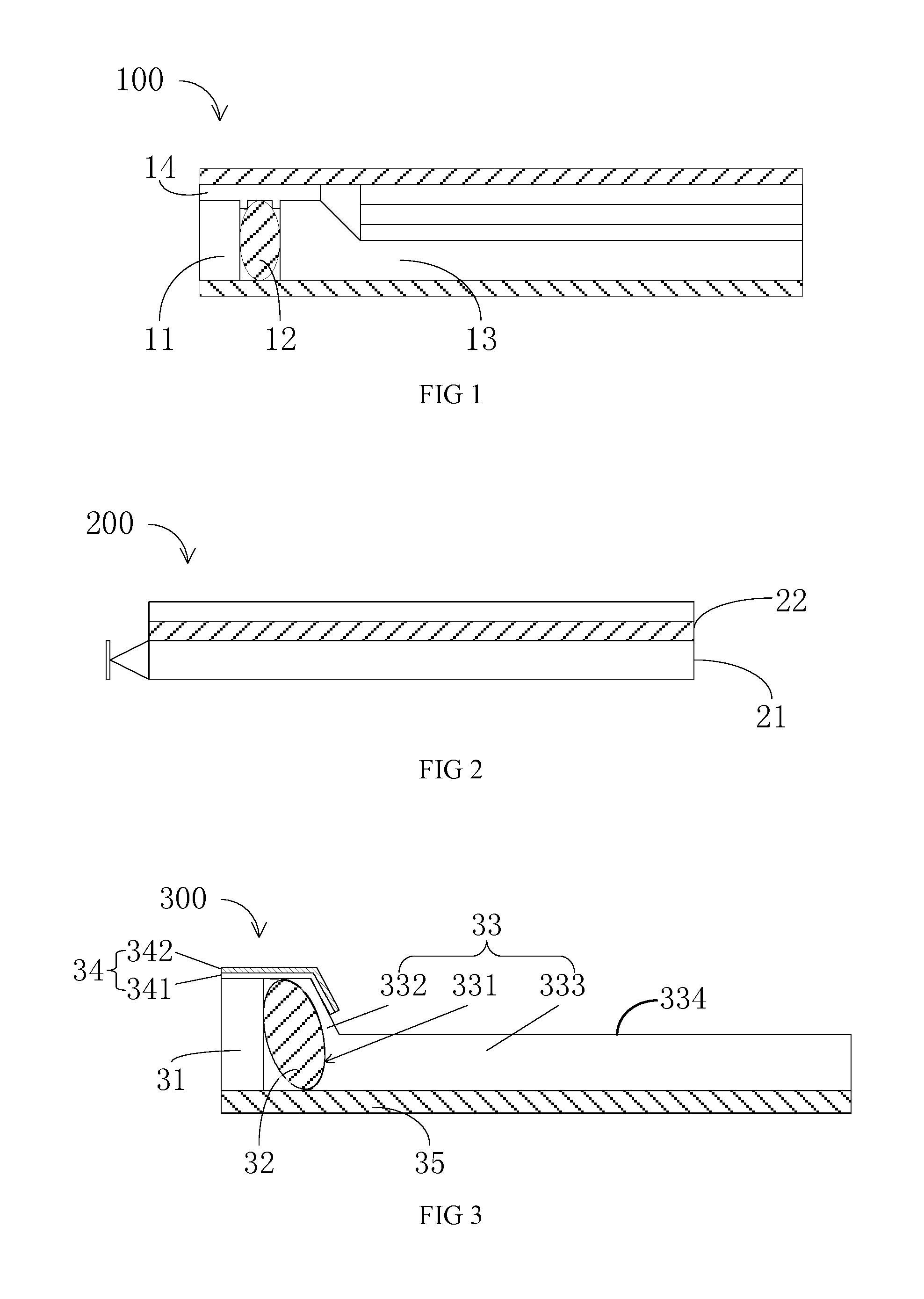
The structure of the backlight module 100 is complex and it is difficult to assemble the backlight module 100.
When manufacturing the sheet 22, the QD material coated in a rim may lead to oxidation due to the air and the water.
In addition, the configuration of the sheet may increase the thickness of the backlight module 200, and thus it is difficult to implement the narrow border and light / thin design.

Method used


Image

  • Backlight modules nad display panels
  • Backlight modules nad display panels
  • Backlight modules nad display panels

Examples


Embodiment Construction

[0036]Embodiments of the invention will now be described more fully hereinafter with reference to the accompanying drawings, in which embodiments of the invention are shown.

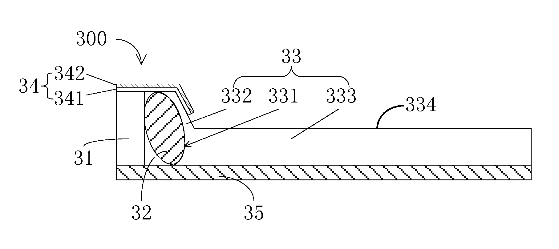
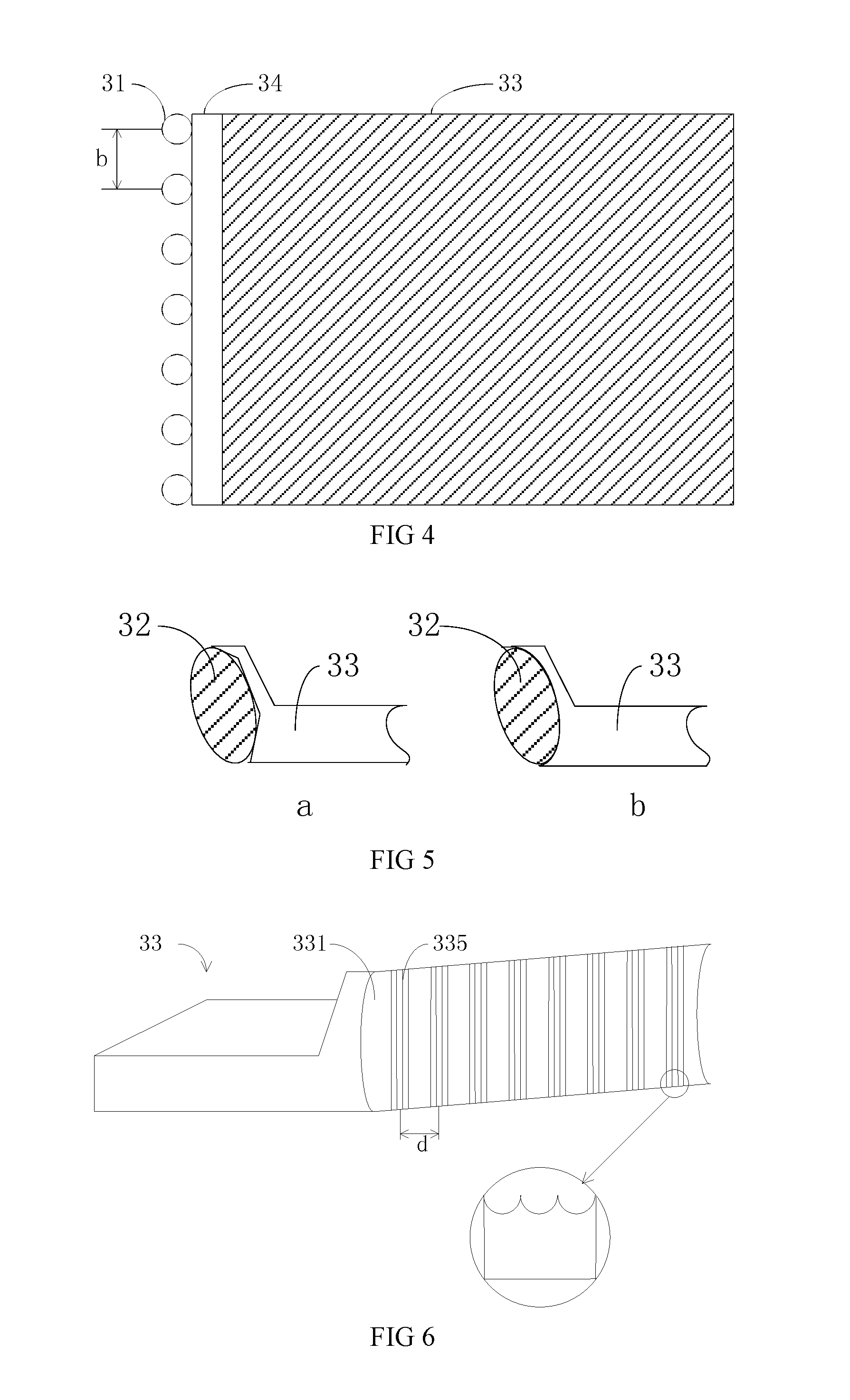
[0037]FIG. 3 is a schematic view of the backlight module in accordance with one embodiment. FIG. 4 is a top view of the backlight module of FIG. 3.

[0038]The backlight module 300 includes a light source 31, a QD tube 32 and a light guiding plate 33. The light source 31 is arranged at a lateral side of the light guiding plate 33. The QD tube 32 is arranged between the light source 31 and the light guiding plate 33.

[0039]The operating process of the backlight module 300 for implementing the high color range requirement will be described hereinafter. The high frequency light beams emitted from the light source 31 enter the QD tube 32 such that the QD material has been activated to generate light beams of different wavelengths. The color of the light beams may be adjusted by configuring the dimension of the QD materia...


PUM


Abstract

The present disclosure relates to a backlight module and a display panel. The backlight module includes a light source, a QD tube and a light guiding plate, the light source being arranged at a lateral side of the light guiding plate, the QD tube being arranged between the light source and the light guiding plate. A light incident surface of the light guiding plate depresses toward an internal of the light guiding plate such that one side of the QD tube is embedded into the light guiding plate and the other side of the QD tube abuts against the light source. The structure is simple and may be easily assembled. In addition, such configuration contributes to the light and thin design.

Description

BACKGROUND OF THE INVENTION[0001]1. Field of the Invention[0002]The present disclosure relates to liquid crystal display technology, and more particularly to a backlight module and a display panel.[0003]2. Discussion of the Related Art[0004]Currently, backlight modules provide backlight for the liquid crystal panels. The backlight module usually include white LED operating as a light source, a light guiding plate, and optical films. The NTSC color range of the liquid crystal panel having such backlight module is around 72%. In order to provide natural color for the displayed images, i.e., to avoid distortion, the display performance having enhanced color range has been expected.[0005]In view of the above object, quantum-dot (QD) backlight source has been developed, which adopts QD material in backlight modules. The light source of high spectrum has replaced the traditional white light LED light source. Basing on the quantum effect, when being radiated by the light source of high spe...

Claims


Application Information

Patent Timeline
Patent Type & Authority Applications(United States)
IPC IPC(8): F21V8/00
CPCG02B6/0026G02B6/0016G02B6/0031G02B6/002G02F1/133615G02F1/133607
Inventor CHENG, YAN
Owner SHENZHEN CHINA STAR OPTOELECTRONICS TECH CO LTD
Learn More