connector

a technology of connecting rods and connector housings, which is applied in the direction of connecting rods, electrical equipment, coupling devices, etc., can solve the problems of low workability of assembling the electric wire cover with the connector housing, and the dimensional accuracy of the portion of the electric wire cover to be assembled with the connector housing becomes lower, and achieves the effect of smooth assembly

Active Publication Date: 2016-12-01
YAZAKI CORP
View PDF34 Cites 12 Cited by
  • Summary
  • Abstract
  • Description
  • Claims
  • Application Information

AI Technical Summary

Benefits of technology

[0007]The present disclosure is made in consideration of the above-mentioned circumstances, and an object of the presen...

Problems solved by technology

If such distortion occurs in the electric wire cover, the dimensional accuracy of the portion of the electric wire cover to be assembled with a co...

Method used


Image

  • connector
  • connector
  • connector

Examples


Embodiment Construction

[0038]An embodiment according to the present disclosure will be described below referring to the accompanying drawings.

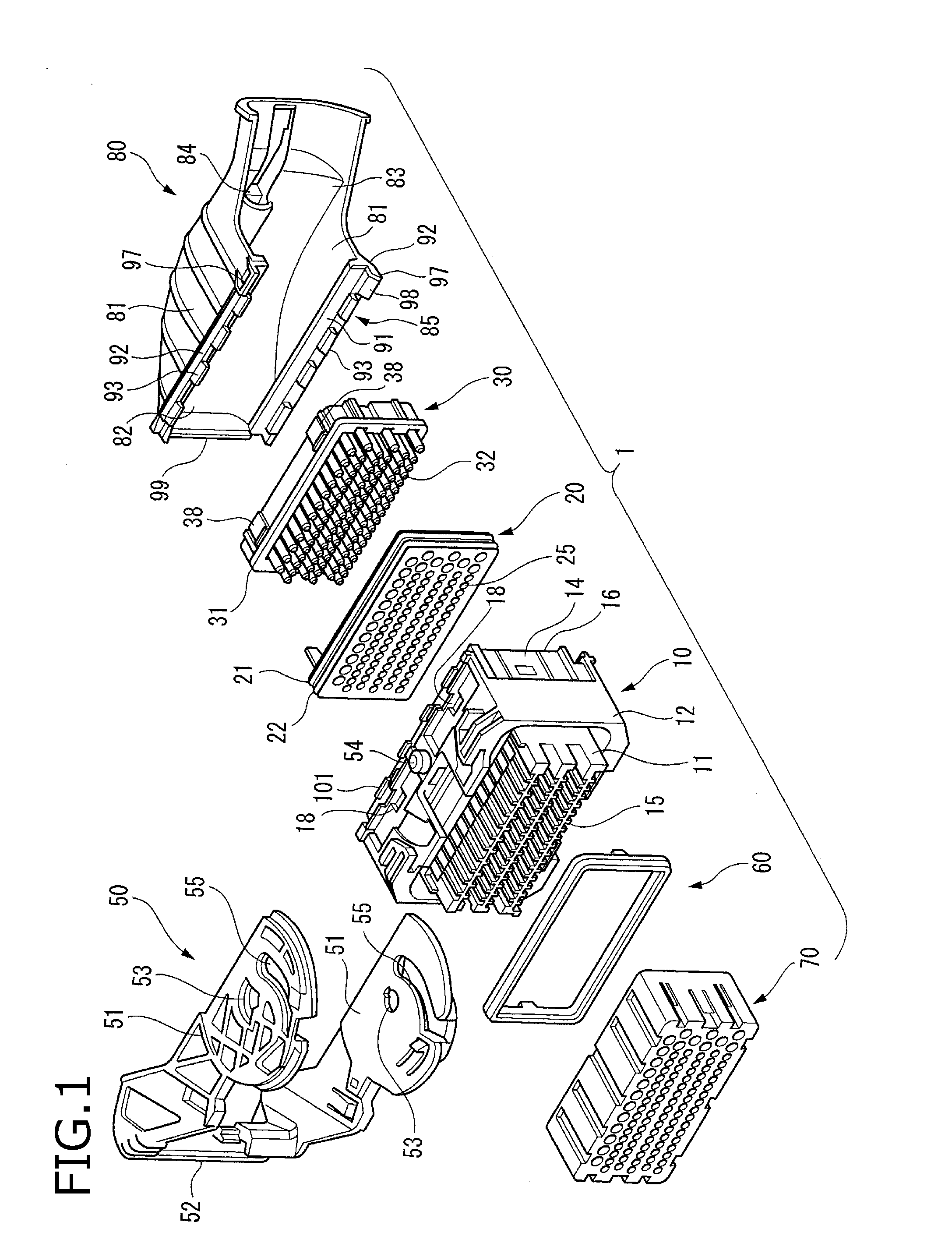
[0039]FIG. 1 is an exploded perspective view showing a connector according to the embodiment of the present disclosure.

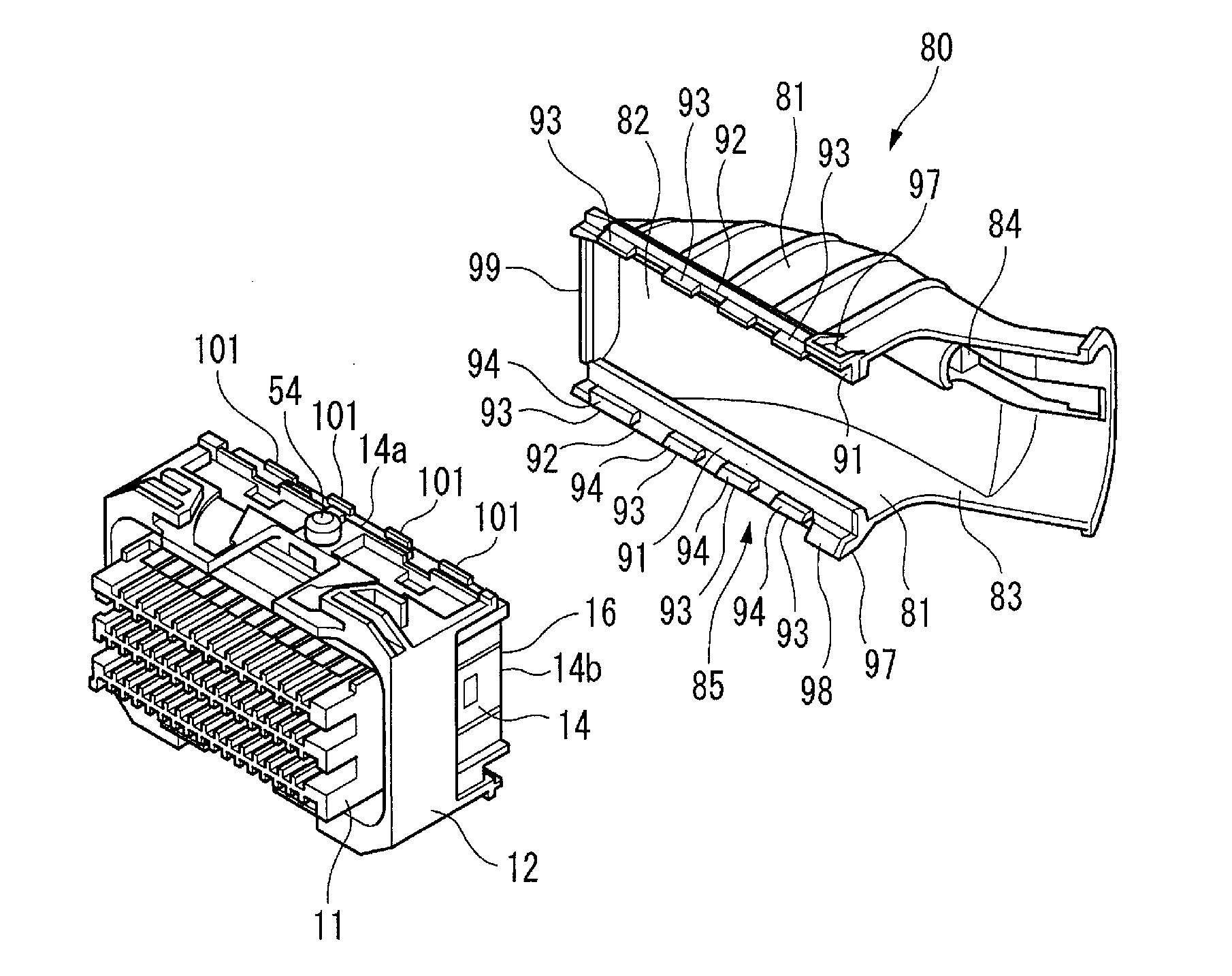
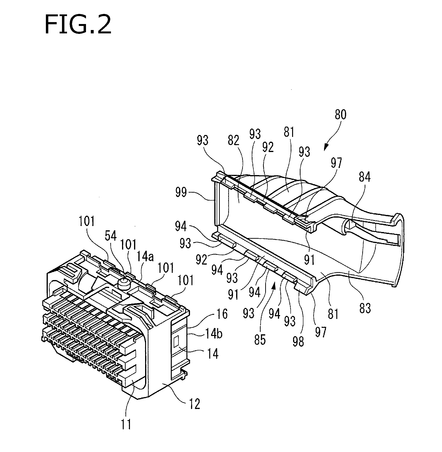
[0040]As shown in FIG. 1, a connector 1 according to the embodiment is equipped with a connector housing (housing) 10 which is made of synthetic resin and in which a plurality of terminals (not shown) are housed from the rear; a mat seal 20 which is made of rubber or flexible resin and is fitted in the rear part of the connector housing 10; a mat seal cover 30 which is made of synthetic resin and fitted in and secured to the rear part of the connector housing 10 to prevent the mat seal 20 from coming off while pressing the mat seal cover 30 from the rear side; a lever 50 which is made of synthetic resin and rotatably mounted on the outside of the connector housing 10; a packing 60 which is inserted into the inside of the connector housing 10 from th...


PUM


Abstract

A connector includes a housing and an electric wire cover assembled with the housing. The housing includes a terminal housing portion and an electric wire leading portion. A locking rib protruding outward is formed on the electric wire leading portion. An assembling portion is formed on an end part of the electric wire cover facing to the housing. The assembling portion includes a locking protrusion and a catching portion protruding more than the locking protrusion in a mounting direction of mounting the electric wire cover on the housing. The catching portion includes a sliding face inclined with respect to the mounting direction. When the electric wire cover is mounted on the housing, the sliding face makes contact with the electric wire leading portion, thereby the assembling portion is displaced outward.

Description

CROSS REFERENCE TO RELATED APPLICATIONS[0001]This application is based on Japanese Patent Application (No. 2015-107803) filed on May 27, 2015, the contents of which are incorporated herein by reference.BACKGROUND OF THE INVENTION[0002]1. Field of the Invention[0003]The present disclosure relates to a connector equipped with an electric wire cover.[0004]2. Description of the Related Art[0005]A connector is known in which an electric wire cover made of resin is mounted to an electric wire leading portion formed at a rear part of a connector housing, bundle of electric wires led out from the electric wire leading portion are protected by this electric wire cover, and the bundle of electric wires is guided in a predetermined direction by the electric wire cover (for example, refer to JP-A-2011-90881).[0006]An electric wire cover made of resin may be distorted sometimes during molding. If such distortion occurs in the electric wire cover, the dimensional accuracy of the portion of the el...

Claims


Application Information

Patent Timeline
IPC IPC(8): H01R13/506H01R9/24
CPCH01R9/2416H01R13/506H01R13/56H01R13/62938
Inventor YAMAKI, SHINSHIBATA, HISAYA
Owner YAZAKI CORP
Why Eureka
Try Eureka