
Fingerprint identification module and electronic equipment

A fingerprint identification module and fingerprint identification technology, which is applied in branch equipment, equipment with sensors, character and pattern recognition, etc., can solve problems such as overflow, insufficient glue dispensing, and increase in the overall size of the fingerprint identification module. Achieve the effect of increasing dispensing volume, improving performance and structural reliability

Active Publication Date: 2019-10-11
HONOR DEVICE CO LTD
View PDF5 Cites 12 Cited by
  • Summary
  • Abstract
  • Description
  • Claims
  • Application Information

AI Technical Summary

Problems solved by technology

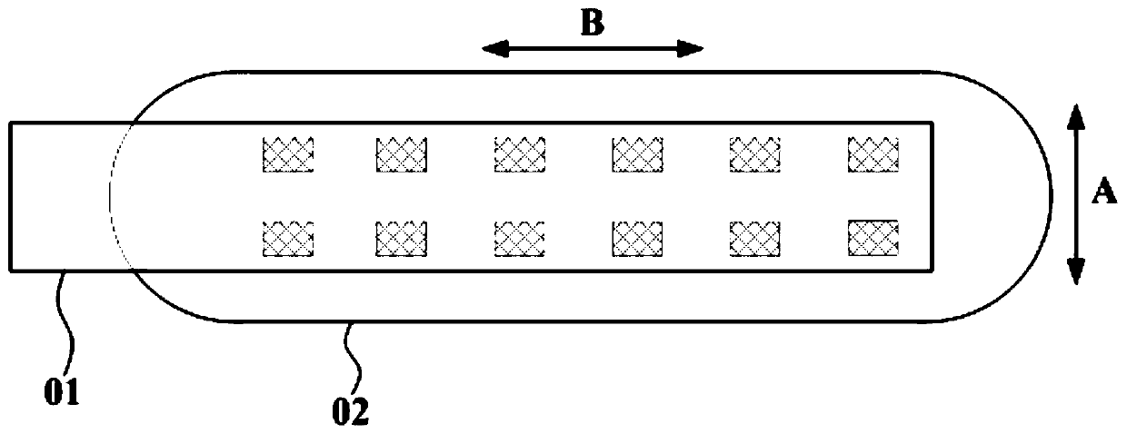
With this design, when forming the glue filling layer, it is necessary to dispense glue on the first surface of the substrate along the extending direction of the edge of the flexible circuit board, so that the glue can be filled between the flexible circuit board and the substrate by capillary action. When it is full, the glue may overflow to the side of the package structure composed of the substrate and the fingerprint identification chip, resulting in an increase in the overall size of the fingerprint identification module, which will interfere with the middle frame when installed in the installation slot
In order to avoid the above problems, the amount of glue dispensing in the existing fingerprint identification modules is generally insufficient, and the insufficient amount of glue dispensing will lead to poor sealing around the pads. Under normal circumstances, the sweat on the fingers easily invades between the flexible circuit board and the substrate and causes corrosion to the pad, which affects the performance of the fingerprint recognition module

Method used


Image

  • Fingerprint identification module and electronic equipment
  • Fingerprint identification module and electronic equipment
  • Fingerprint identification module and electronic equipment

Examples


Embodiment Construction

[0033] In order to make the purpose, technical solution and advantages of the application clearer, the application will be further described in detail below in conjunction with the accompanying drawings.

[0034] At present, with the widespread application of fingerprint recognition technology in the field of electronic devices, various electronic devices can implement functions such as screen unlocking, fast payment, and file encryption based on this technology, which greatly improves user experience. Taking a mobile phone as an example, in the specific setting, the fingerprint identification area is usually set on the side of the screen of the mobile phone, and an installation slot is opened on the front cover of the mobile phone corresponding to the fingerprint identification area to accommodate the fingerprint identification module used to realize the above functions. Group. With the emergence of full-screen mobile phones, the fingerprint recognition area gradually shifts ...


PUM


Abstract

The invention provides a fingerprint identification module and electronic equipment, and aims to improve the performance and structural reliability of the fingerprint identification module. The fingerprint recognition module comprises a flexible circuit board, a substrate, a fingerprint recognition chip and a filling adhesive layer, the flexible circuit board and the substrate are arranged in a stacked mode and comprise a first end and a second end which are opposite in position, at least one end of the first end and the second end exceeds the substrate, and a wire outlet area is formed at theend, close to the end exceeding the substrate, of the flexible circuit board; the first surface, facing the flexible circuit board, of the substrate comprises a first area and a second area, the first area is provided with a wire and a bonding pad used for being electrically connected with the flexible circuit board, and the second area is opposite to the wire outlet area and provided with an open groove. The fingerprint identification chip is arranged on the second surface, back to the flexible circuit board, of the substrate; and the filling adhesive layer is filled between the flexible circuit board and the substrate and is used for wrapping the bonding pad.

Description

technical field [0001] The present application relates to the technical field of electronic equipment, in particular to a fingerprint identification module and an electronic equipment. Background technique [0002] With the continuous advancement of the full-screen design of mobile phones, the fingerprint recognition area of ​​the mobile phone is gradually shifted from the side of the mobile phone screen to the back side or peripheral side of the mobile phone. In this way, it is necessary to set an installation slot on the back shell or middle frame of the mobile phone to accommodate fingerprints. Identify mods. The fingerprint identification module usually includes a flexible circuit board, a substrate, a fingerprint identification chip, and a filling glue layer. Connected pads, the fingerprint identification chip is arranged on the second surface of the substrate facing away from the flexible circuit board and forms an integrated packaging structure with the substrate, an...

Claims


Application Information

Patent Timeline
Patent Type & Authority Applications(China)
IPC IPC(8): G06F1/16G06K9/00H04M1/02
CPCG06F1/1684H04M1/026G06F1/1626G06V40/13H01L2224/48091H01L2224/73265H01L2224/32225H01L2924/181H04M2250/12H04M1/236G06V40/1306G06F1/1671G06F1/26H01L2924/00014H01L2924/00012
Inventor 王道虎李彤彤周琛徐偲伟王勇
Owner HONOR DEVICE CO LTD
Learn More