Cementing manifold with canister fed dart and ball release system

a cementing manifold and canister-fed technology, which is applied in the direction of drilling casings, drilling pipes, borehole/well accessories, etc., can solve the problems of consuming valuable rig space, storing the cementing manifold on the drilling rig, and not being able to fit in standard racks

Inactive Publication Date: 2008-12-04
SMITH INT INC
View PDF12 Cites 26 Cited by
  • Summary
  • Abstract
  • Description
  • Claims
  • Application Information

AI Technical Summary

Problems solved by technology

Thus, given the weight and size of the cementing manifold, lifting it into position, which may be 20-30 feet above the rig floor, raises concerns for the safety of rig personnel.
Rotation of the drilling string is again interrupted to allow rig personnel to traverse the thirty or so feet above the rig floor to the cementing manifold and manually actuate valves on the cementing manifold to release the sphere and darts This too raises safety concerns.
While this flag is designed to be visible from the rig floor, resetting the flag r...

Method used


Image

  • Cementing manifold with canister fed dart and ball release system
  • Cementing manifold with canister fed dart and ball release system
  • Cementing manifold with canister fed dart and ball release system

Examples


Embodiment Construction

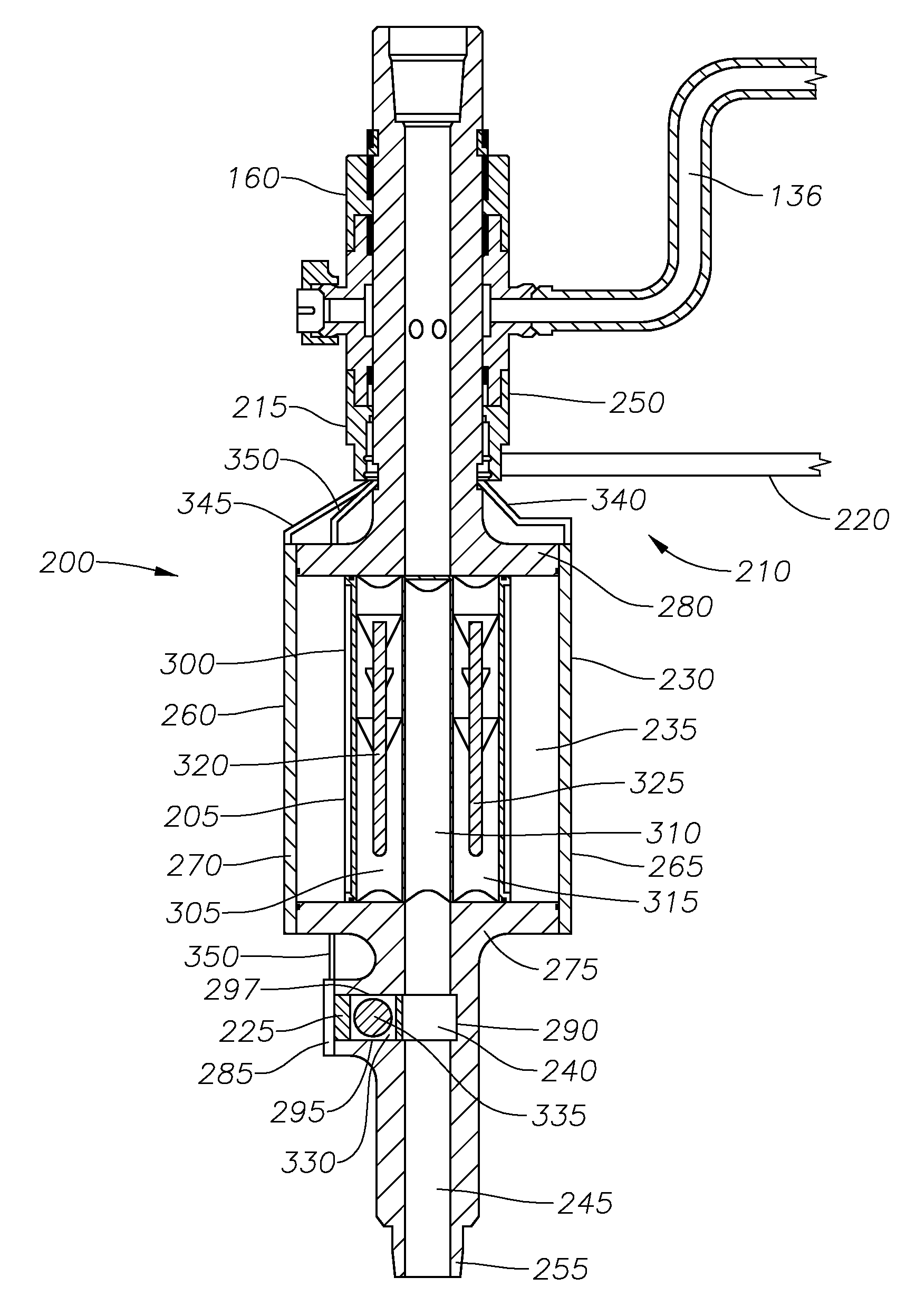
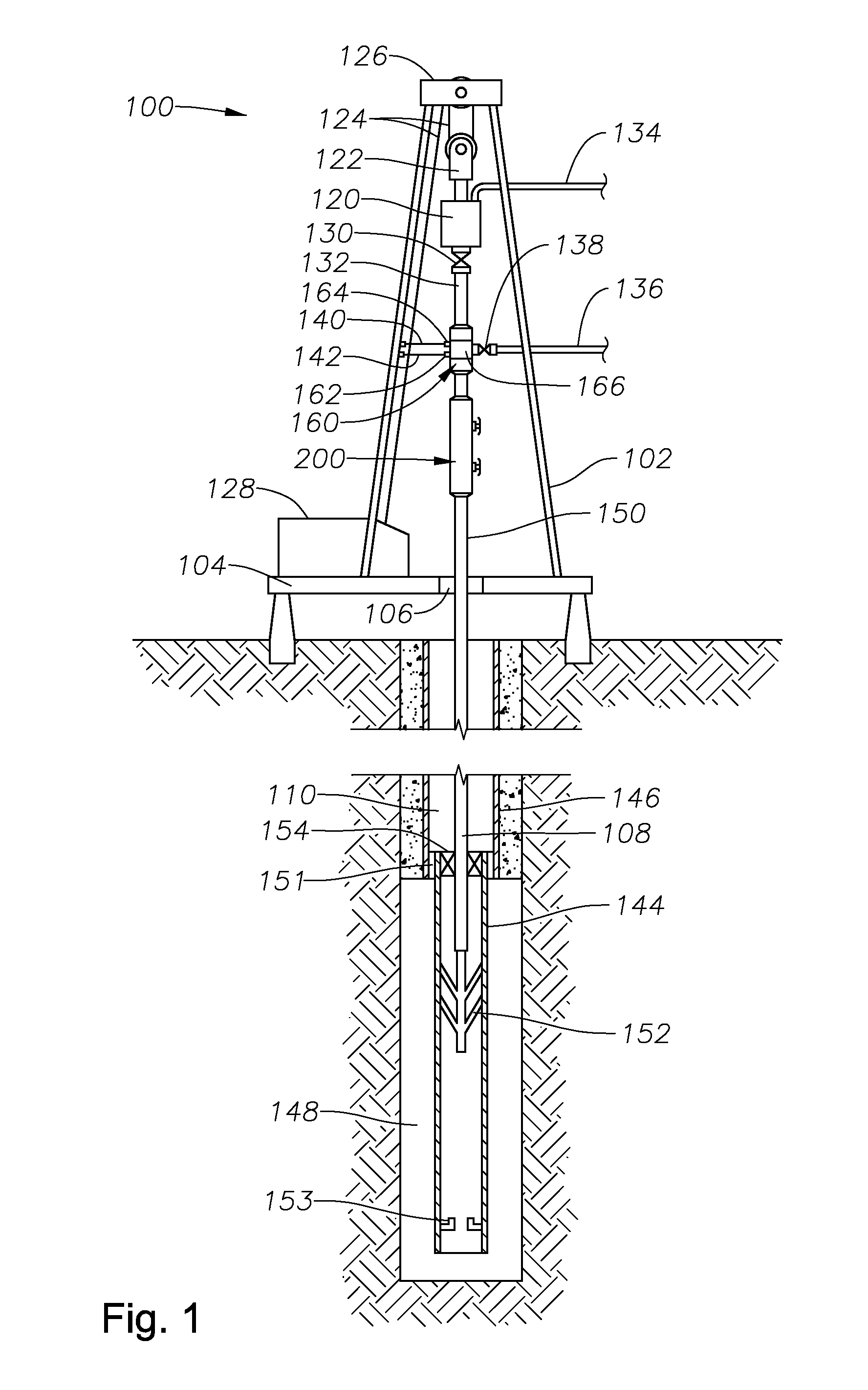
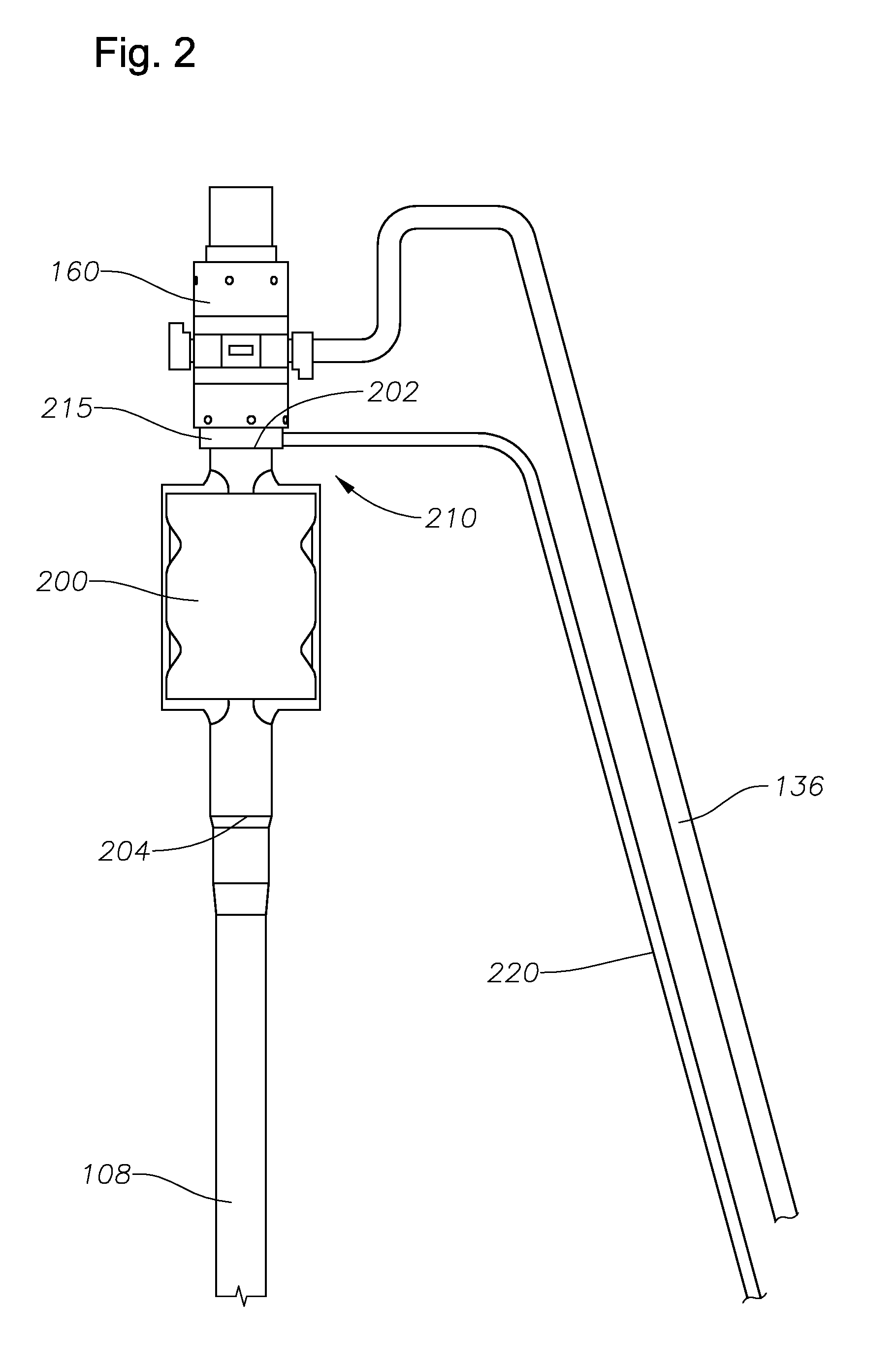
[0017]Apparatus and methods for cementing tubulars in a borehole are disclosed. In some embodiments, the downhole apparatus includes a housing, a cartridge disposed within the housing, and an actuator. The housing includes a fluid entry port and a fluid exit port. The cartridge includes a first chamber and is moveable between a first and a second position. In the fist position, the first chamber is out of fluid communication with the entry port and the exit port. In the second position, the first chamber is in fluid communication with the entry port and the exit port. The actuator is adapted to move the cartridge between the first and second positions.

[0018]Some method embodiments for cementing tubulars in a borehole include providing a cement manifold having a through-passage in fluid communication with a tubing string which includes the tubulars, providing a cartridge disposed in the cement manifold, storing a projectile in the cartridge and isolated from the through-passage, conv...


PUM


Abstract

Apparatus and methods for cementing tubulars in a borehole are disclosed In some embodiments, the apparatus includes a housing, a cartridge disposed within the housing, and an actuator. The housing includes a fluid entry port and a fluid exit port The cartridge includes a first chamber and is moveable between a first and a second position In the first position, the first chamber is out of fluid communication with the entry port and the exit port. In the second position, the first chamber is in fluid communication with the entry port and the exit port. The actuator is adapted to move the cartridge between the first and second positions.

Description

CROSS-REFERENCE TO RELATED APPLICATIONS[0001]Not Applicable.STATEMENT REGARDING FEDERALLY SPONSORED RESEARCH OR DEVELOPMENT[0002]Not Applicable.BACKGROUND[0003]1. Field of Art[0004]The present invention relates generally to apparatus and methods for cementing downhole tubulars into a well bore. More particularly, the present invention relates to a cementing manifold and method of use.[0005]2. Description of Related Art[0006]A well-known method of drilling hydrocarbon wells involves disposing a drill bit at the end of a drill string and rotating the drill string from the surface utilizing either a top drive unit or a rotary table set in the drilling rig floor. As the well is formed, it is desirable to line the well bore. Thus, as drilling continues, progressively smaller diameter tubulars comprising casing and / or liner strings may be installed end-to-end to line the drilled borehole. As the well is drilled deeper, each string is run through and secured to the lower end of the previou...

Claims


Application Information

Patent Timeline
IPC IPC(8): E21B33/13E21B19/20E21B33/05
CPCE21B33/05
Inventor PEER, RICHARD DAVIDCOSTO, JR., ROBERT JAMES
Owner SMITH INT INC
Why Eureka
Try Eureka