
Projector and control method thereof

a technology of projector and control method, which is applied in the direction of projector, light source, instruments, etc., can solve the problems of lamp replacement worker making a wrong setting, causing burst failure or the like, and preparing a lamp of a different lamp size than the selected lamp size by mistake, so as to achieve the effect of proper driving control of the lamp

Active Publication Date: 2008-12-04
SONY CORP
View PDF44 Cites 10 Cited by
  • Summary
  • Abstract
  • Description
  • Claims
  • Application Information

AI Technical Summary

Benefits of technology

The present invention provides a projector that can load lamps of multiple kinds, each with a unique serial code formed by arranging lamp information including minimum and maximum wattage and a check sum. The projector includes a control circuit that sets a driving range for the lamp power supply based on the code range of the loaded lamp, and controls the lamp power supply within that range. This ensures proper driving control for the lamp, reducing the risk of failure due to current exceeding the rated current. The invention also provides a method for controlling the lamp power supply in the projector. Overall, the invention improves the reliability and safety of replacing lamps in projectors.

Problems solved by technology

However, in this case, the lamp replacing worker may make a wrong setting through an operation mistake, or select a wrong lamp.
In such a case, there is a danger of a current exceeding a rated current flowing through the lamp and thus a burst failure or the like occurring.
A reason that the lamp size does not match the setting of the lamp power supply unit may be that the selection of the lamp size itself is wrong, or that although the selection of the lamp size itself is correct, a lamp of a lamp size different from the selected lamp size is prepared by mistake because lamps are generally identical or similar in shape.
In addition, when a lamp of a lamp size that does not perfectly match the set range of the lamp power supply unit prepared in advance is loaded into the existing projector, even use of the lamp is not possible in the first place.

Method used

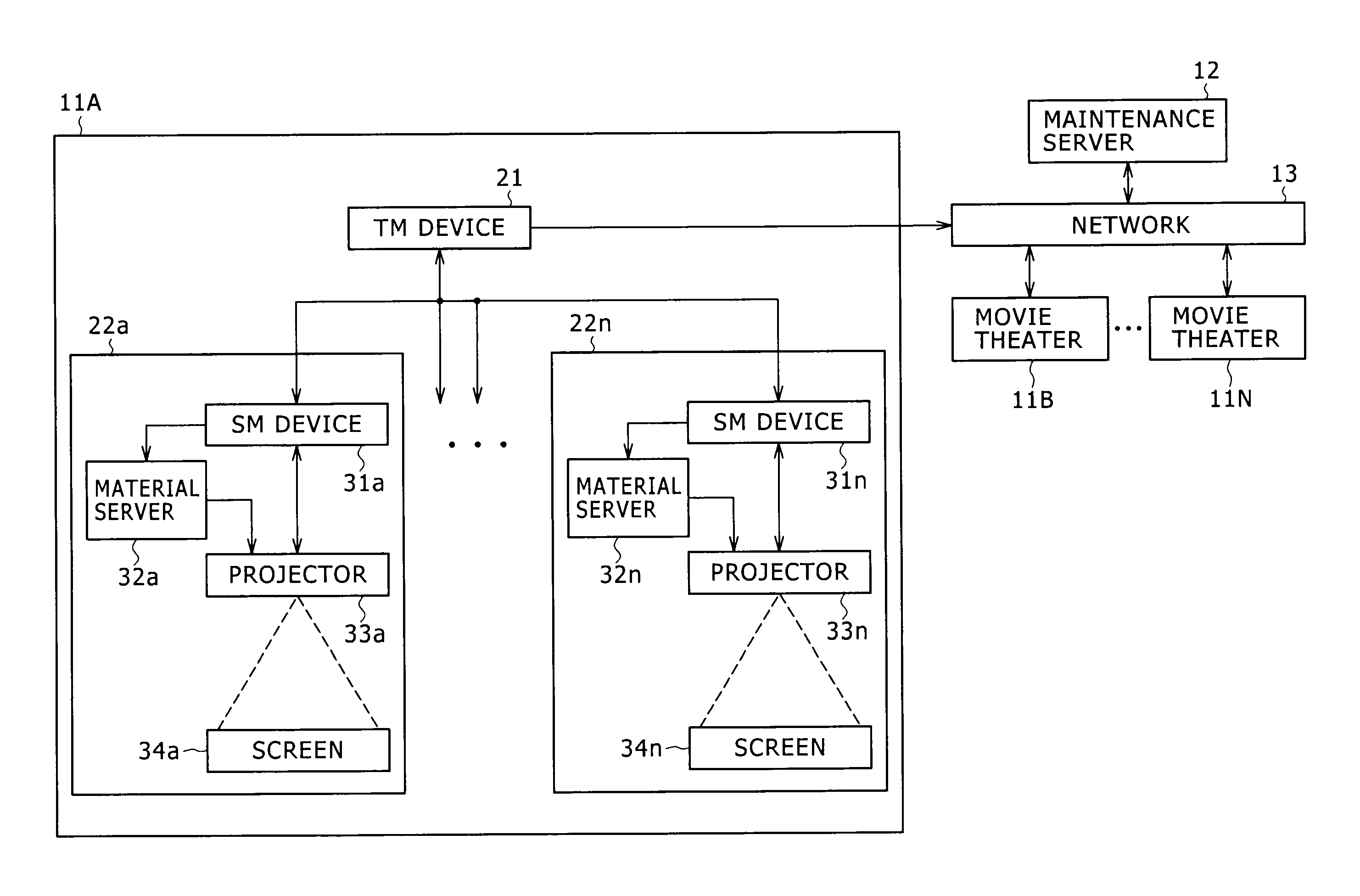
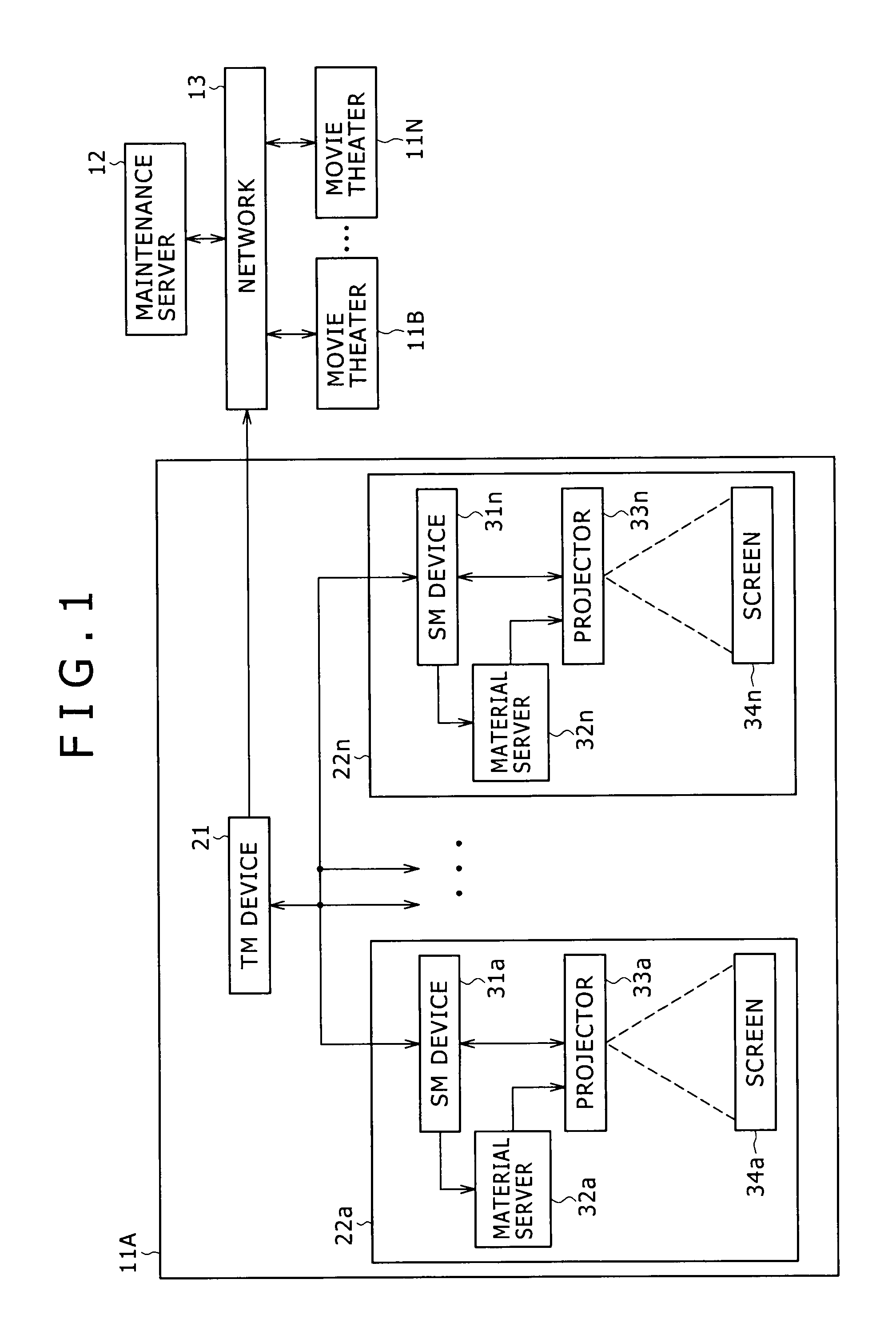

Image

  • Projector and control method thereof
  • Projector and control method thereof
  • Projector and control method thereof

Examples


Embodiment Construction

[0030]Preferred embodiments of the present invention will hereinafter be described. Correspondences between constitutional requirements of the present invention and embodiments described in the detailed description of the invention are illustrated as follows. This description is to confirm that embodiments supporting the present invention are described in the detailed description of the invention. Therefore, even when there is an embodiment described in the detailed description of the invention but not described here as corresponding to a constitutional requirement, it does not signify that the embodiment does not correspond to the constitutional requirement. Conversely, even when an embodiment is described here as corresponding to a constitutional requirement, it does not signify that the embodiment does not correspond to constitutional requirements other than that constitutional requirement.

[0031]Further, this description does not signify that inventions corresponding to concrete ...

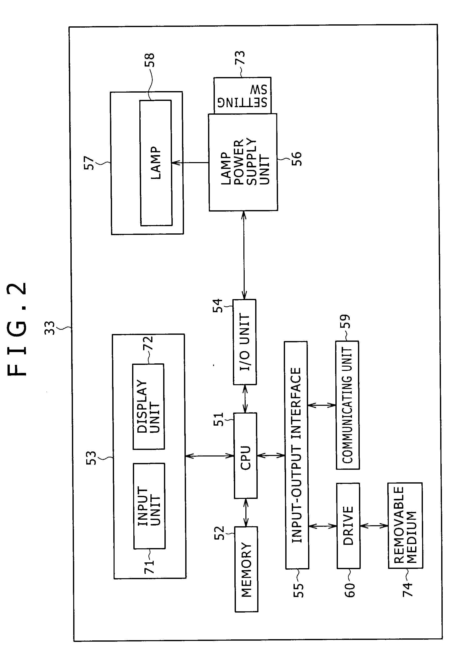

PUM


Abstract

Disclosed herein is a projector that can be loaded with lamps of a plurality of kinds, each of a plurality of the lamps loadable into the projector being given a lamp serial code formed by arranging lamp information including at least a minimum wattage and a maximum wattage of the lamp and a check sum in predetermined order, the projector including: a lamp power supply for driving the lamp loaded in the projector, the lamp power supply being provided in advance with a plurality of mode ranges each as a range from a minimum wattage to a maximum wattage of output of the lamp power supply, and one predetermined mode range of the plurality of mode ranges being freely set in the lamp power supply; and a control circuit for controlling the lamp power supply.

Description

CROSS REFERENCES TO RELATED APPLICATIONS[0001]The present invention contains subject matter related to Japanese Patent Applications JP 2007-060435, JP 2007-060437, and JP 2007-060439, these filed with the Japan Patent Office on Mar. 9, 2007, the entire contents of which being incorporated herein by reference.BACKGROUND OF THE INVENTION[0002]1. Field of the Invention[0003]The present invention relates to a projector and a control method thereof, and particularly to a projector and a control method thereof that properly assist in an operation of replacing a lamp in a projector, whereby proper driving control for the lamp can be realized.[0004]2. Description of the Related Art[0005]Recently, with the development of video display technology, a projector applicable to a field of so-called digital cinema, that is, a projector usable for a purpose of screening a movie in a movie theater has appeared (see Japanese Patent Laid-Open No. Hei 5-260423, for example).[0006]As such a projector, th...

Claims


Application Information

Patent Timeline
Patent Type & Authority Applications(United States)
IPC IPC(8): G03B21/20
CPCG03B21/20G03B21/206G03B21/2026
Inventor SHIRASU, TOSHIYUKIOKA, DAIZONAGUMO, HIROBUMIISHIDA, TESSHO
Owner SONY CORP
Learn More