Driving apparatus, and lens apparatus and image pickup apparatus including the same

a technology of driving apparatus and lens, which is applied in the direction of printers, cameras, instruments, etc., can solve the problems of inaccurate rotational position and rotational speed of motor derived based on detection results of position detectors, excessive rotational speed of motors, and operator's discomfort with images, etc., to suppress the influence of gear train backlash and accurate lens drive control

Active Publication Date: 2017-05-30
CANON KK
View PDF10 Cites 0 Cited by
  • Summary
  • Abstract
  • Description
  • Claims
  • Application Information

AI Technical Summary

Benefits of technology

[0009]In view of the above, it is an object of the present invention to provide a driving apparatus capable of performing accurate lens drive control by suppressing influence of a backlash of a gear train of a lens driving mechanism without using two or more position detectors for controlling a single movable optical member, and to provide a lens apparatus and an image pickup apparatus including the lens driving apparatus.
[0011]According to the one embodiment of the present invention, it is possible to provide the driving apparatus suppressed in the influence of the backlash of the gear train of the lens driving mechanism without using two or more position detectors for controlling the single movable optical member, and to provide the lens apparatus and the image pickup apparatus including the lens driving apparatus.

Problems solved by technology

However, the position detector configured to detect the lens position is influenced by a backlash of a gear train of a lens driving mechanism, and hence the rotational position and rotational speed of a motor derived based on detection results of the position detector are inaccurate.
As a result, the rotational speed of motor is increased excessively, which may cause an operator to feel uncomfortable with an image at the start of lens movement.
Therefore, at least two position detectors are necessary to control a single movable optical member, thereby raising such problems that the apparatus is upsized and the manufacturing cost is increased.

Method used


Image

  • Driving apparatus, and lens apparatus and image pickup apparatus including the same
  • Driving apparatus, and lens apparatus and image pickup apparatus including the same
  • Driving apparatus, and lens apparatus and image pickup apparatus including the same

Examples


first embodiment

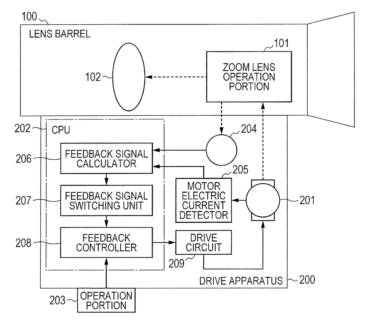
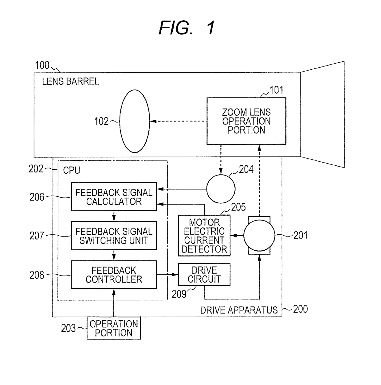
[0024]FIG. 1 illustrates a configuration of a lens apparatus according to a first embodiment of the present invention.

[0025]The lens apparatus includes a lens barrel 100 and a drive apparatus 200. The lens barrel 100 includes a zoom lens operation portion 101 illustrated in FIG. 1, an image pickup optical system including optical adjusting members such as a zoom lens 102, a focus lens (not shown), and an iris (not shown), and an operation unit for the optical adjusting members. The zoom lens102 being one of the optical adjusting members is hereinafter described as a movable optical member to be driven in the present invention.

[0026]The drive apparatus 200 includes a motor 201 (drive unit), a CPU 202, an operation portion 203, a position detector 204 (position detector), a motor electric current detector 205, and a drive circuit 209. The CPU 202 includes a feedback signal calculator 206 (first deriving unit), a feedback signal switching portion 207 (selection unit), and a feedback co...

second embodiment

[0051]Now, a second embodiment of the present invention is described with reference to FIGS. 6 to 8.

[0052]In the first embodiment, based on the change in position of the zoom lens operation portion 101, the feedback signal switching portion 207 determines whether or not the motor 201 is rotated through the backlash area, to thereby switch between the signal including the zoom lens position and speed (first information) and the signal including the rotational position and rotational speed of the motor (second information) to use as the feedback signal for the drive control.

[0053]In this embodiment, as a method of determining whether or not the motor 201 is rotated through the backlash area, the feedback signal switching portion 207 compares a driving direction indicated by the command information and a drive direction of the zoom lens operation portion 101 in the previous operation. Based on a result of the comparison, the feedback signal switching portion 207 switches between the zo...

third embodiment

[0061]Now, a third embodiment of the present invention is described with reference to FIGS. 9 and 10.

[0062]In the second embodiment, based on whether the zoom lens operation portion 101 is driven in a reverse direction or a forward direction, the feedback signal switching portion 207 determines whether or not the motor 201 is rotated through the backlash area.

[0063]In this embodiment, as a method of determining whether or not the motor 201 is rotated through the backlash area, the feedback signal switching portion 207 compares a drive direction indicated by the command signal (command information) and a gravity direction of the zoom lens 102. Based on a result of the comparison, the feedback signal switching portion 207 switches whether to output the zoom lens position and speed or the rotational position and rotational speed of the lens.

[0064]Further, in this embodiment, in order to eliminate influence of delay to be imposed on the operability, when the drive speed indicated by the...


PUM


Abstract

A driving apparatus connected to a lens barrel including a movable optical member to drive the movable optical member, includes: a drive unit driving the movable optical member; a controller controlling the drive unit; a first deriving unit deriving a first information indicating at least one of position or speed of the movable optical member; and a second information indicating at least one of position or speed of the drive unit based on a counter-electromotive voltage generated through the drive of the drive unit; and a selection unit to select the first information or the second information as a selected information according to a state of a backlash of the drive unit, the controller controlling the drive unit based on: the first information or the second information selected by the selection unit; and the command information to direct driving of the movable optical member.

Description

BACKGROUND OF THE INVENTION[0001]Field of the Invention[0002]The present invention relates to a driving apparatus, and more particularly, to a driving apparatus configured to drive a lens, and a lens apparatus and an image pickup apparatus including the lens driving apparatus.[0003]Description of the Related Art[0004]When a lens is to be driven by a drive apparatus, a lens position is detected by a position detector, and a control signal for eliminating a difference between the detected position and a target position determined based on a position command value is transmitted to a motor, to thereby drive the lens toward the target position (position feedback control). Further, a lens speed determined based on the position detected by the position detector is reflected on a value to be output to the motor, to thereby drive the lens at a constant speed (speed feedback control).[0005]However, the position detector configured to detect the lens position is influenced by a backlash of a ...

Claims


Application Information

Patent Timeline
Patent Type & Authority Patents(United States)
IPC IPC(8): G02B7/09G03B13/34H04N5/232G02B7/10
CPCG02B7/09G02B7/102G03B13/34H04N5/23296H04N23/69
Inventor MAKITA, KEISUKE
Owner CANON KK
Why Eureka
Try Eureka