Dynamic link aggregation

a dynamic link and aggregation technology, applied in the field of dynamic link aggregation in the communications network, can solve the problems of limited load balancing and utilization of the link bandwidth

Active Publication Date: 2008-12-04
CISCO TECH INC
View PDF6 Cites 85 Cited by
  • Summary
  • Abstract
  • Description
  • Claims
  • Application Information

AI Technical Summary

Problems solved by technology

Static link aggregation does not take into account the size of frames or amount of traffic assigned to each port, ...

Method used


Image

  • Dynamic link aggregation
  • Dynamic link aggregation
  • Dynamic link aggregation

Examples


example embodiments

[0012]The following description is presented to enable one of ordinary skill in the art to make and use the invention. Descriptions of specific embodiments and applications are provided only as examples and various modifications will be readily apparent to those skilled in the art. The general principles described herein may be applied to other embodiments and applications without departing from the scope of the invention. Thus, the present invention is not to be limited to the embodiments shown, but is to be accorded the widest scope consistent with the principles and features described herein. For purpose of clarity, details relating to technical material that is known in the technical fields related to the invention have not been described in detail.

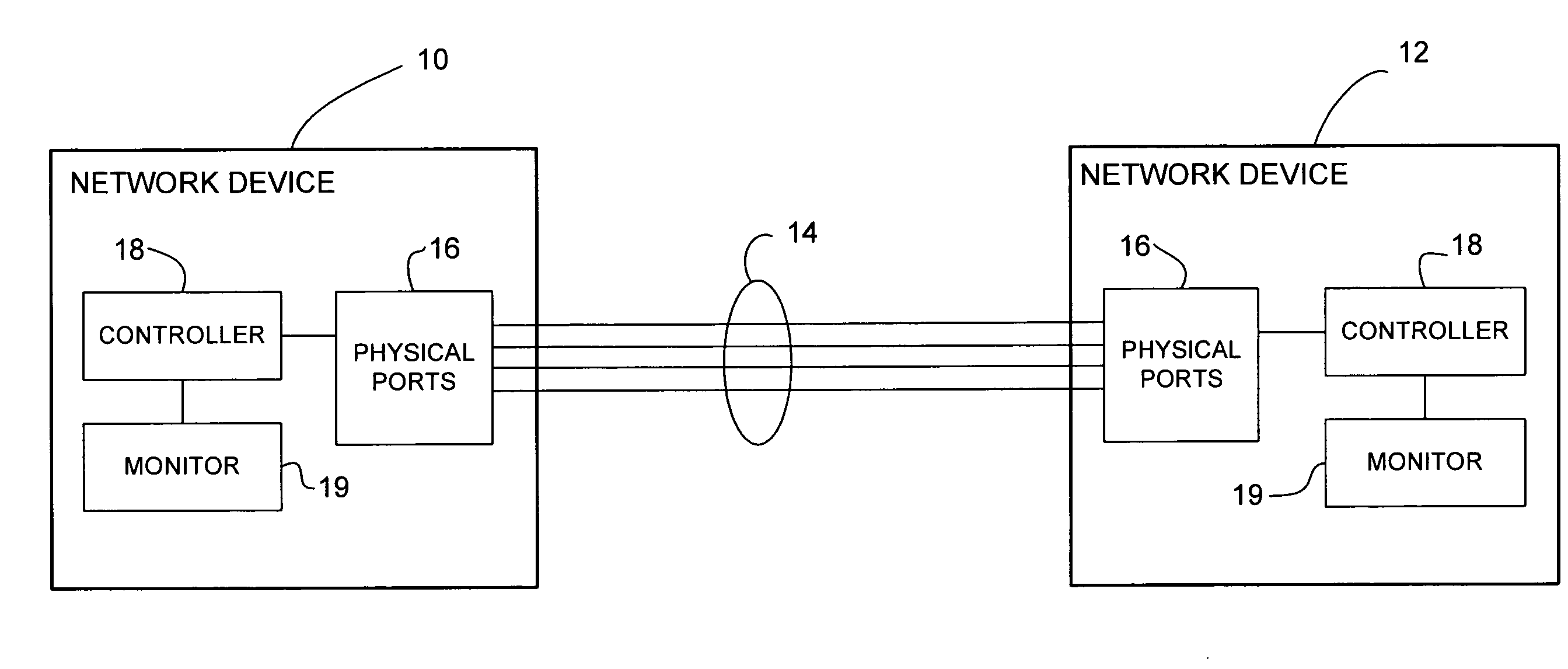
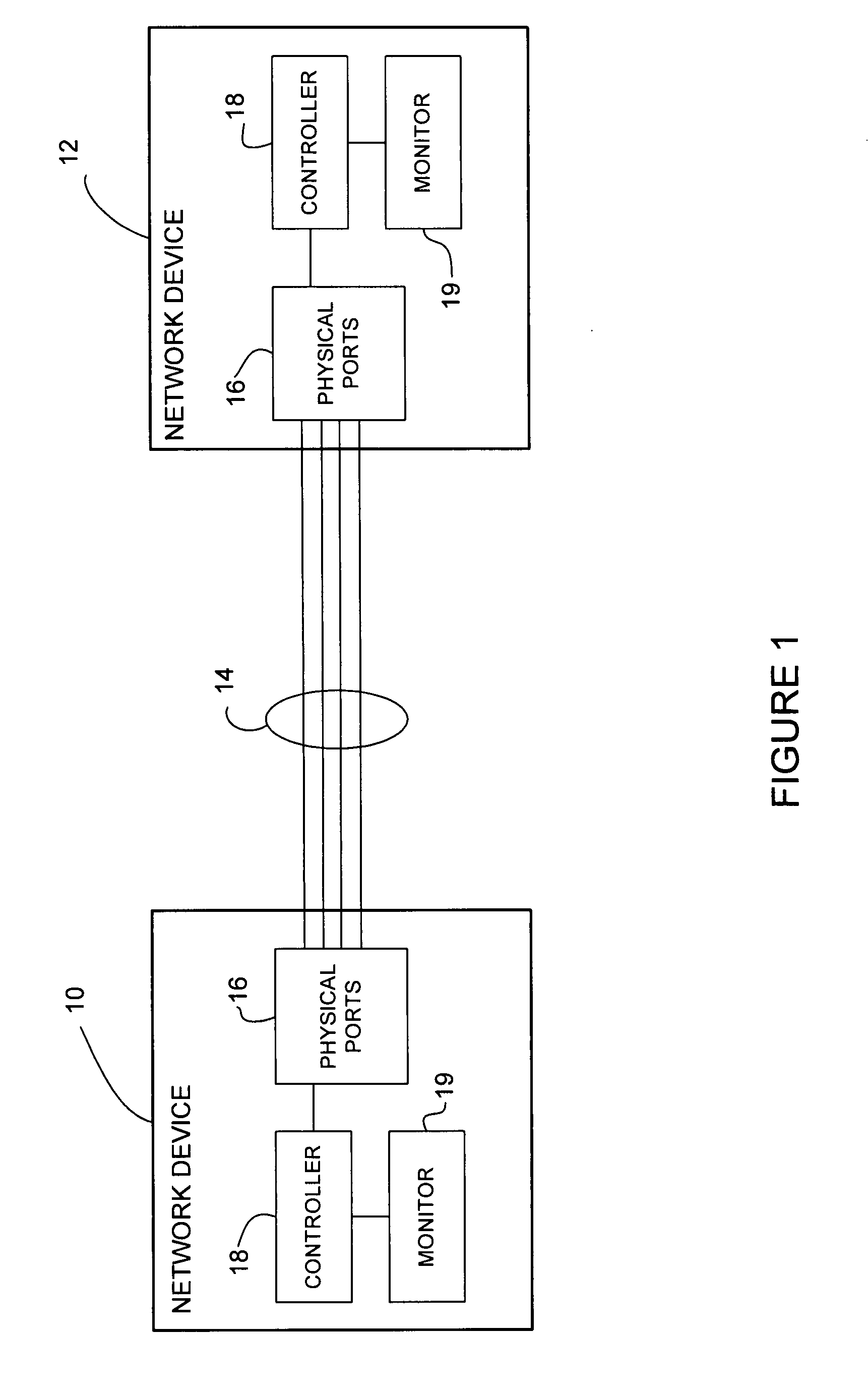
[0013]Referring now to the drawings, and first to FIG. 1, an example of a network that may implement embodiments described herein is shown. The embodiments operate in the context of a data communication network including multiple netw...


PUM


Abstract

A method and apparatus for dynamically distributing traffic over links grouped together in a data transmission channel are disclosed. In one embodiment, the method includes receiving data at the network device, distributing the data over a first array, mapping the first array to a second array having entries corresponding to the links, and measuring data traffic. The mapping between the first array and the second array is updated based on traffic measurements to balance traffic load over the links.

Description

BACKGROUND OF THE INVENTION[0001]The present disclosure relates generally to dynamic link aggregation in a communications network.[0002]Network devices are interconnected by communication links for transmitting data packets through physical ports. In order to provide redundancy or bandwidth, some networks bundle multiple communication links between a pair of network devices. Link Aggregation Control Protocol (LACP) is part of an IEEE specification (802.3ad) that allows several physical ports to be bundled together to form a single logical channel. The logical channel has multiple links that connect the network infrastructure device and the network device.[0003]One example of such link aggregation implementation is EtherChannel. In conventional EtherChannel, load sharing is statically configured. EtherChannel frame distribution is based on an algorithm that selects a port based on addresses and session information. For example, the frame distribution may be based on a source address,...

Claims


Application Information

Patent Timeline
IPC IPC(8): H04L12/26
CPCH04L47/10H04L47/125H04L45/245
Inventor ERVIN, JIMMYRAMPAL, SANJEEV
Owner CISCO TECH INC
Why Eureka
Try Eureka