Method for manipulating a dental virtual model, method for creating physical entities based on a dental virtual model thus manipulated, and dental models thus created

Active Publication Date: 2008-12-04
ALIGN TECH
View PDF13 Cites 78 Cited by
  • Summary
  • Abstract
  • Description
  • Claims
  • Application Information

AI Technical Summary

Problems solved by technology

However, it is often the case that when scanning the intra oral cavity to obtain 3D data of the preparation and finish line on which the virtual model is based, part of the finish line, and possibly also the shoulder and other parts of the preparation, may be obscured by soft tissues such as the gum that, no longer being pushed by the dental surfaces that have been removed, deform to cover at least a part of the finish line on the prepared dental site.

Method used


Image

  • Method for manipulating a dental virtual model, method for creating physical entities based on a dental virtual model thus manipulated, and dental models thus created
  • Method for manipulating a dental virtual model, method for creating physical entities based on a dental virtual model thus manipulated, and dental models thus created
  • Method for manipulating a dental virtual model, method for creating physical entities based on a dental virtual model thus manipulated, and dental models thus created

Examples


Embodiment Construction

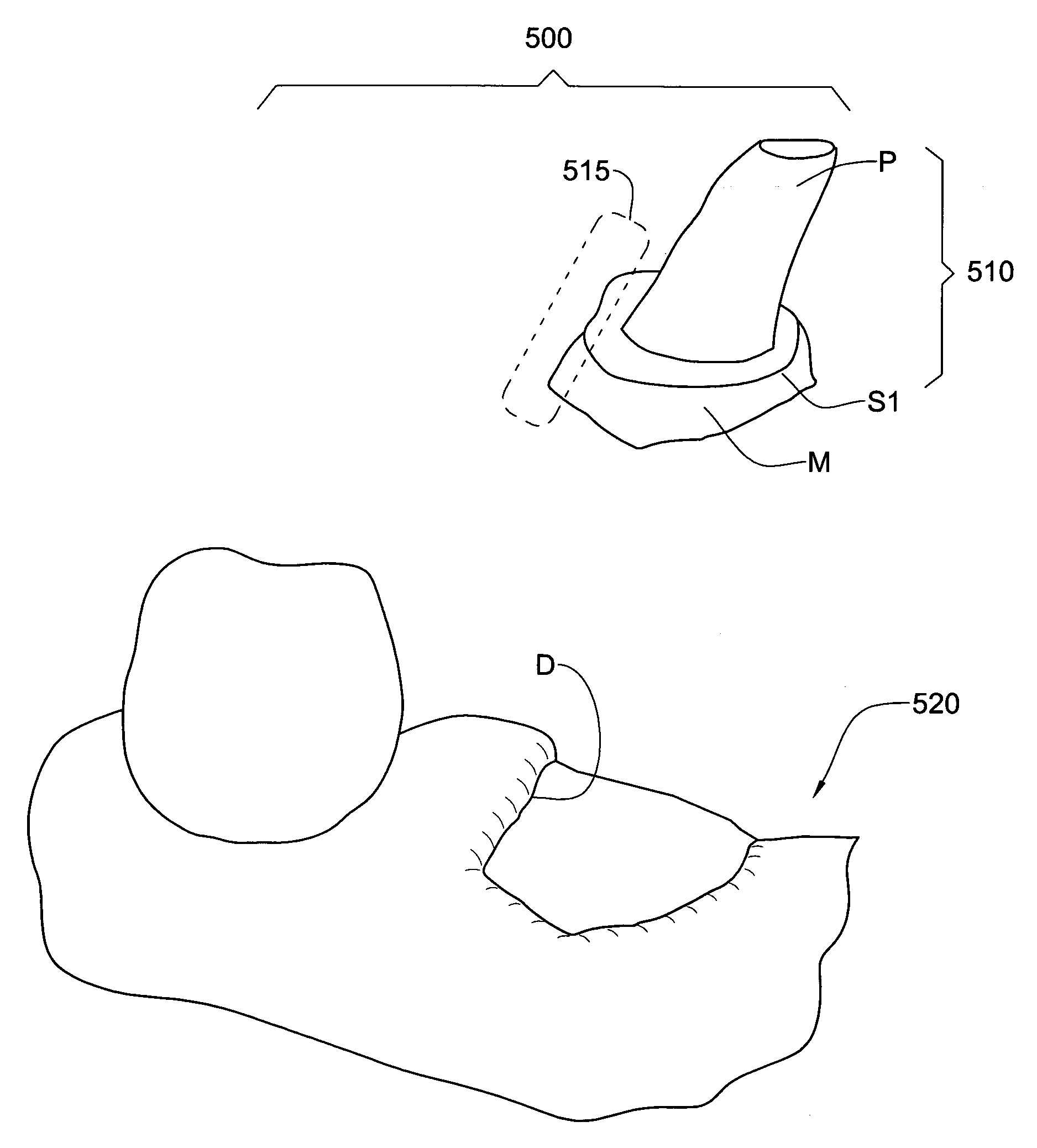
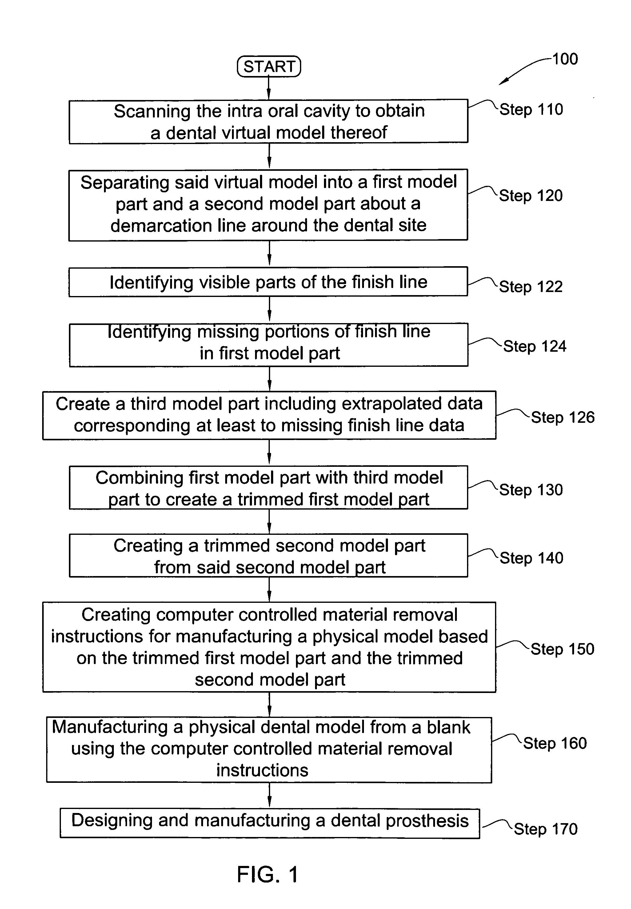
[0066]A computer-based method for manipulating a virtual dental model, particularly useful for defining a finish line (also referred to herein as “margin line”), according to the invention is illustrated in FIG. 1. Accordingly, acquiring an accurate 3D representation (herein also referred to as “three-dimensional model”, “3D model”, “virtual model” and the like) of the intraoral cavity is the first step 110 that is carried out by the method 100. This first virtual model is generally designated with the numeral 500 in the accompanying figures.

[0067]The target parts of the intraoral cavity that are to be scanned are first identified. The target parts are the parts (also referred to interchangeably as zones or areas) of the intraoral cavity 200 which form the focus of a particular dental procedure for a particular patient and regarding which it is desired to obtain the 3D topographical or surface data thereof. The target parts typically include the part of the tooth or the teeth on whi...


PUM

PropertyMeasurementUnit
coloraaaaaaaaaa
depth dimensionaaaaaaaaaa
depthaaaaaaaaaa

Abstract

A 3D virtual model of an intra oral cavity in which at least a part of a finish line of a preparation is obscured is manipulated in virtual space by means of a computer or the like to create, recreate or reconstruct finish line data and other geometrical corresponding to the obscured part. Trimmed virtual models, and trimmed physical models, can then be created utilizing data thus created. The virtual models and / or the physical models may be used in the design and manufacture of copings or of prostheses.

Description

[0001]This application is a continuation application of U.S. Patent Application Ser. No. 11 / 349,124, filed Feb. 8, 2006, which claims priority from Provisional Patent Application No. 60 / 699,499, filed on Jul. 15, 2005, the entire contents of which are hereby incorporated in their entirety.FIELD OF THE INVENTION[0002]This invention relates to dentistry and in particular to computer-aided methods associated with prosthodontics.BACKGROUND OF THE INVENTION[0003]There are many procedures associated with the oral cavity in which a precise three-dimensional representation of the cavity is very useful to the dental practitioner.[0004]Such representations enable the practitioner to study the cavity of individual patients in a similar manner to the study of the traditional plaster model. More importantly, three-dimensional numerical entities of the dental cavity also allow the practitioner to study methods or approaches when dealing with particular dental problems of any given patient, and fo...

Claims


Application Information

Patent Timeline
Patent Type & Authority Applications(United States)
IPC IPC(8): G05B19/18G06G7/48A61C5/10A61C5/77
CPCA61C13/0004Y10T29/49567A61C13/34G06F17/50G16H50/50A61C5/77G16H30/40Y02P90/02G16H40/63G06F30/00G06T19/20G06T2219/2004A61C9/004G16H30/20
Inventor KOPELMAN, AVITAUB, ELDAD
Owner ALIGN TECH
Why Eureka
Try Eureka