Hydraulic Unit

a technology of hydraulic units and fluids, applied in the direction of fluid couplings, positive displacement liquid engines, couplings, etc., can solve the problems of changing the oil level in the reservoir, the opening of at least one individual pump, etc., and achieve the effect of small delivery rate and/or volume flow, large volume flow, and small volum

Active Publication Date: 2008-12-11
WAGNER VERMOGENSVERWALTUNGS GMBH & CO KG
View PDF8 Cites 4 Cited by
  • Summary
  • Abstract
  • Description
  • Claims
  • Application Information

AI Technical Summary

Benefits of technology

[0007]The hydraulic unit according to the invention is in particular suitable in cases where consumers with different consumption capabilities are connected. If a consumer is a hydraulic power wrench for turning screws and bolts, the load to be overcome by the hydraulic pressure is normally high such that the delivery rate and / or the volume flow are small. A different scenario is provided if a connected consumer is a piston-cylinder unit, for example, whose large-volume cylinder includes a piston which is moved against a small load. Here, a resultant rapid piston movement produces a large volume flow. The large volume flow results in a change of the oil level in the reservoir, wherein the upper individual pumps are possibly not submerged for a short time. Such a condition is prevented by the auxiliary reservoir.
[0010]According to a preferred aspect of the invention, the auxiliary reservoir is hermetically sealed above the oil level, and a connecting line connects the auxiliary reservoir with a vented additional tank at a location below the oil level. Here, the auxiliary reservoir and the additional tank define a communicating system. The atmospheric pressure causes oil to be fed from the vented tank to the auxiliary reservoir when oil is withdrawn from the auxiliary reservoir to flow to the reservoir. The additional tank increases the volume of the auxiliary reservoir, but, on the other hand, is spatially separated from the auxiliary reservoir. The auxiliary reservoir is arranged above the reservoir, while the additional tank may be located below the reservoir. The additional tank may thus define a base for the housing of the reservoir.

Problems solved by technology

Use of a multiple piston pump, where the individual pumps are arranged in a specific array in the reservoir, involves the risk that, when the oil level decreases, the intake opening of at least one individual pump is temporarily not submerged and takes in air.
The large volume flow results in a change of the oil level in the reservoir, wherein the upper individual pumps are possibly not submerged for a short time.
On the other hand, without an auxiliary reservoir there would be the risk that due to the cross section narrowing in upward direction, the upper region having a small volume would rapidly be emptied and remain so when a large quantity of oil is withdrawn.

Method used


Image

  • Hydraulic Unit
  • Hydraulic Unit
  • Hydraulic Unit

Examples


Embodiment Construction

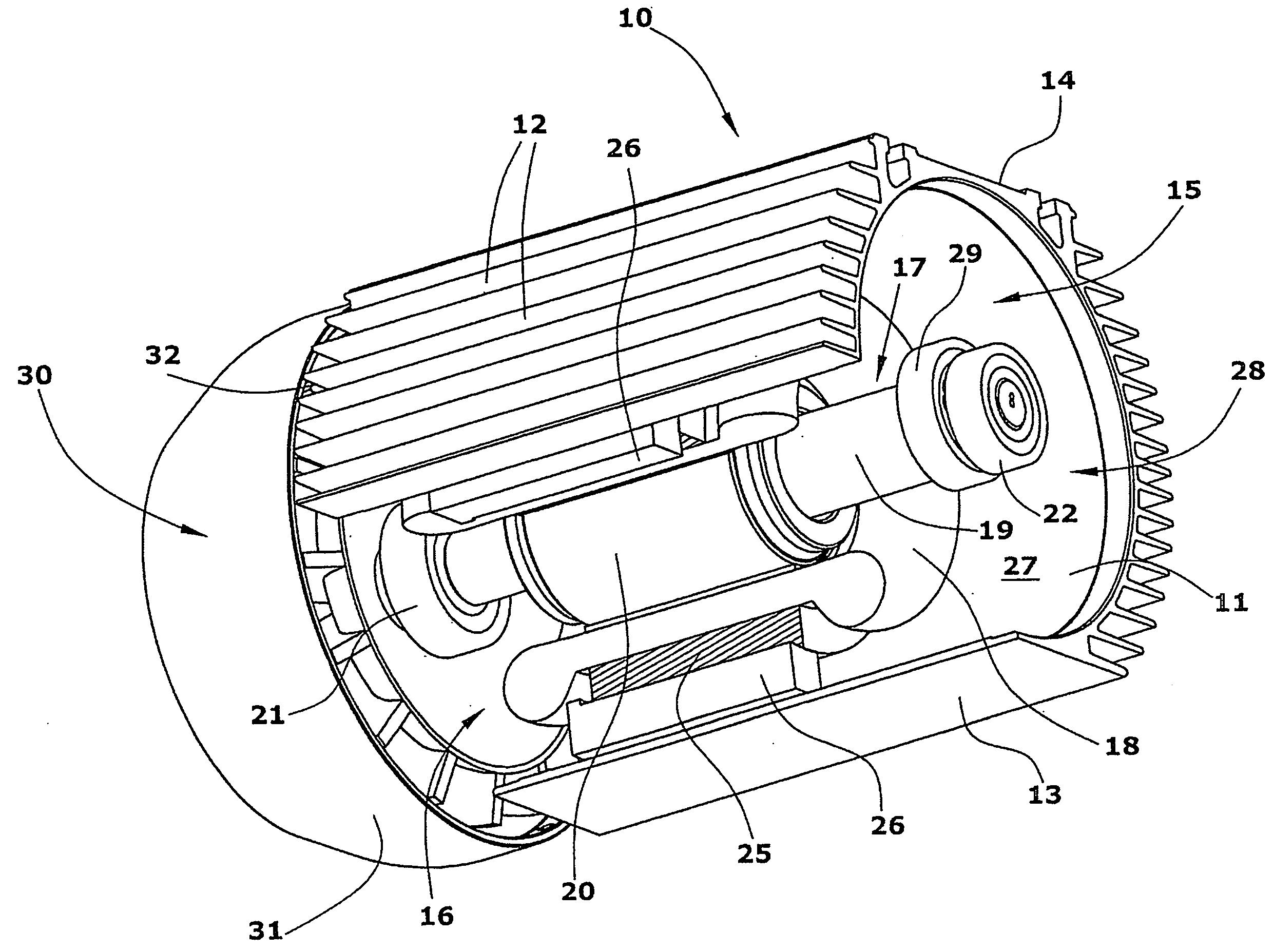
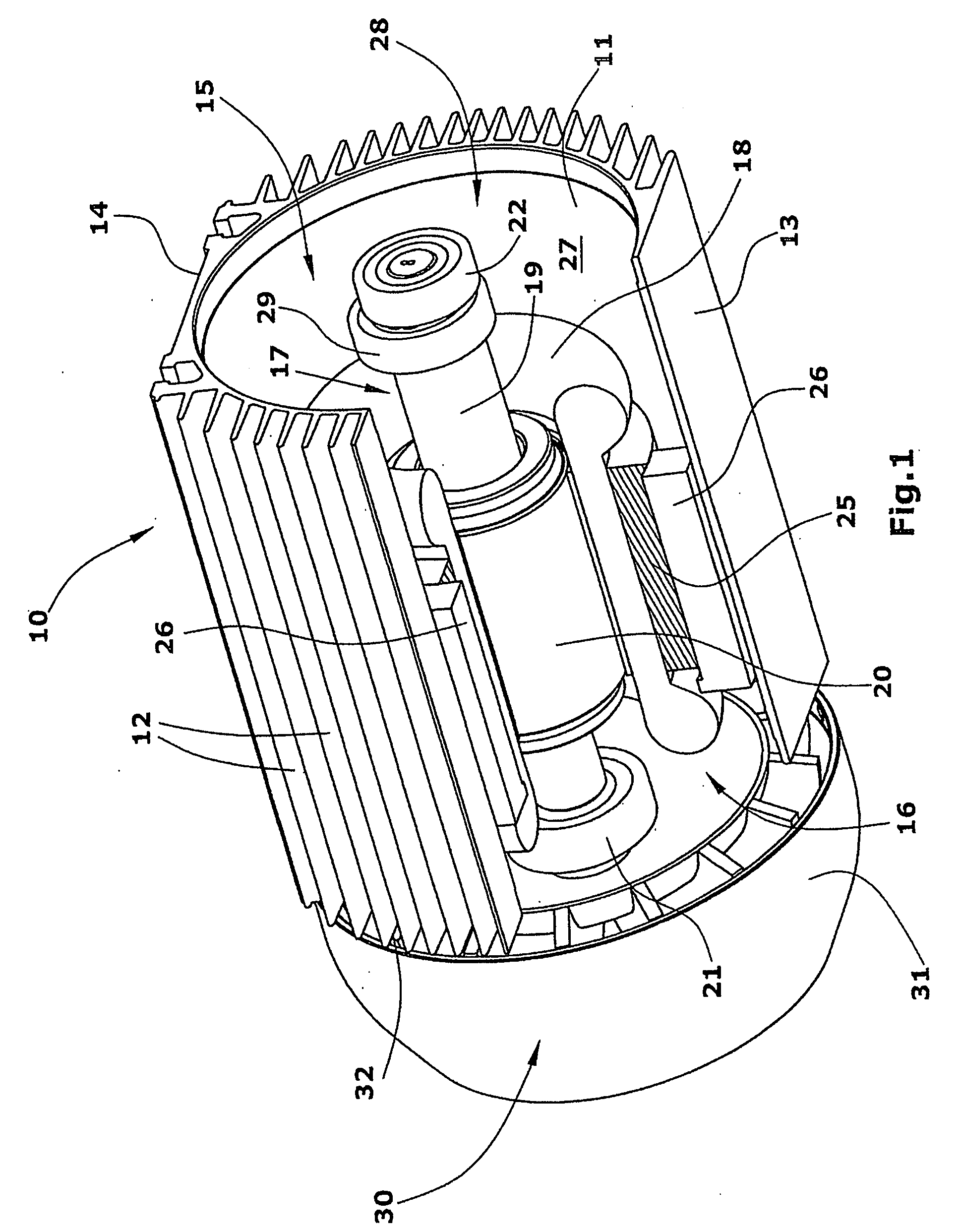
[0018]As shown in FIG. 1, the hydraulic unit comprises a housing 10 which is a conventional motor housing of an electric motor. The housing 10 has a cylindrical inner wall 11 and comprises on its outside numerous longitudinal ribs 12 defining cooling ribs. The housing 10 is configured as a profile body composed of an extruded profile. At one location on its circumference the housing 10 is provided with a longitudinal mounting plate 13 attached thereto, and diametrically opposed a fastening profile 14 for attaching components to the housing is located.

[0019]The housing 10 comprises an electric motor 15. Said electric motor 15 includes a stator 16 and a rotor 17. The motor is a permanently excited synchronous motor whose stator comprises a rotating field-generating stator winding 18. The rotor 17 includes a motor shaft 19 and permanent magnets 20 fastened thereto. The motor shaft 19 is supported in bearings 21,22 located in the front walls (not shown) of the housing 10.

[0020]The stato...


PUM


Abstract

The invention relates to a hydraulic group comprising a reservoir (28) for oil, in which a multiple piston pump (60) is arranged. The individual pumps (61) are cyclically driven by an eccentric ring (29). In order to ensure a permanent immersion of the individual pumps in the reservoir (28), an auxiliary reservoir (47) providing oil for refilling the reservoir (28) is arranged above the reservoir. The auxiliary reservoir (47) is connected to an additional tank (45) by means of a connection line (48).

Description

BACKGROUND OF THE INVENTION[0001]The invention relates to a hydraulic unit comprising an oil-containing reservoir which includes a motor and a pump driven by said motor.[0002]A hydraulic unit comprises a pump acting as a pressure generator, said pump taking in oil from a reservoir and supplying said oil to a consumer. A return line extends from the consumer back to the reservoir. Hydraulic units are known which comprise a motor configured as a submersible motor arranged in the reservoir and submerged in the hydraulic fluid. The heat generated in the motor is discharged via the hydraulic oil.BACKGROUND OF THE INVENTION[0003]It is an object of the invention to provide a hydraulic unit which is capable of supplying defined variable volume flows without the risk of air aspiration.[0004]The hydraulic unit according to the present invention is defined in claim 1. Said unit comprises a multiple piston pump composed of individual pumps arranged in a specific array, wherein the reservoir has...

Claims


Application Information

Patent Timeline
Patent Type & Authority Applications(United States)
IPC IPC(8): F16D31/02
CPCF04B23/021
Inventor ANDRES, GUNTERSITTIG, ULFTHELEN, BERNDWAGNER, PAUL-HEINZ
Owner WAGNER VERMOGENSVERWALTUNGS GMBH & CO KG
Why Eureka
Try Eureka