Boundary acoustic wave device

a technology of acoustic waves and devices, applied in the direction of impedence networks, electrical devices, etc., can solve the problems of degrading the resonant, increasing the overall size and increasing the cost of the surface acoustic wave devi

Active Publication Date: 2007-04-26
MURATA MFG CO LTD
View PDF9 Cites 35 Cited by
  • Summary
  • Abstract
  • Description
  • Claims
  • Application Information

AI Technical Summary

Benefits of technology

[0015] In order to overcome the problems described above, preferred embodiments of the present invention provide a boundary acoustic wave device in which the electromechanical coefficient, which is a main response of an SH boundary acoustic wave, is large, the transmission loss and the power flow angle are small, and a spurious signal caused by a Stoneley wave in the vicinity of the main response is small.

Problems solved by technology

When the package having a cavity portion as described above is used, the cost of the surface acoustic wave device is inevitably increased.
In addition, since the size of the package is much larger than that of the surface acoustic wave element, the overall size of the surface acoustic wave device is inevitably increased.
The loss caused by the propagation of a boundary acoustic wave, that is, the propagation loss, may degrade the insertion loss of a boundary acoustic wave filter or may also degrade the resonant resistance or the impedance ratio of a boundary acoustic wave resonator, the impedance ratio being a ratio between the impedance at a resonant frequency and that at an antiresonant frequency.
Hence, electrode designing becomes complicated.
In addition, the loss caused by the deviation in angle is liable to be generated.
Furthermore, when an operating frequency of a boundary acoustic wave device is changed by the temperature, the practical pass band and stop band are decreased in the case of a boundary acoustic wave filter.
In the case of a resonator, when an oscillation circuit is provided, the above change in operating frequency caused by the temperature results in abnormal oscillation.
Furthermore, when Si was actually disposed in the [001]-Si(110) direction as the proposed optimum condition, a bonding process with a high degree of difficulty had to be performed as disclosed in Japanese Unexamined Patent Application Publication No. 10-84247.
In general, in the case of a wafer having a diameter of 3 inches or more, which is used for mass production, it has been difficult to uniformly bond wafers together by a bonding process.
In addition, after the wafer bonding is carried out, when cutting is performed to form chips, inconveniences such as peeling are liable to occur.

Method used


Image

  • Boundary acoustic wave device
  • Boundary acoustic wave device
  • Boundary acoustic wave device

Examples


experimental example 1

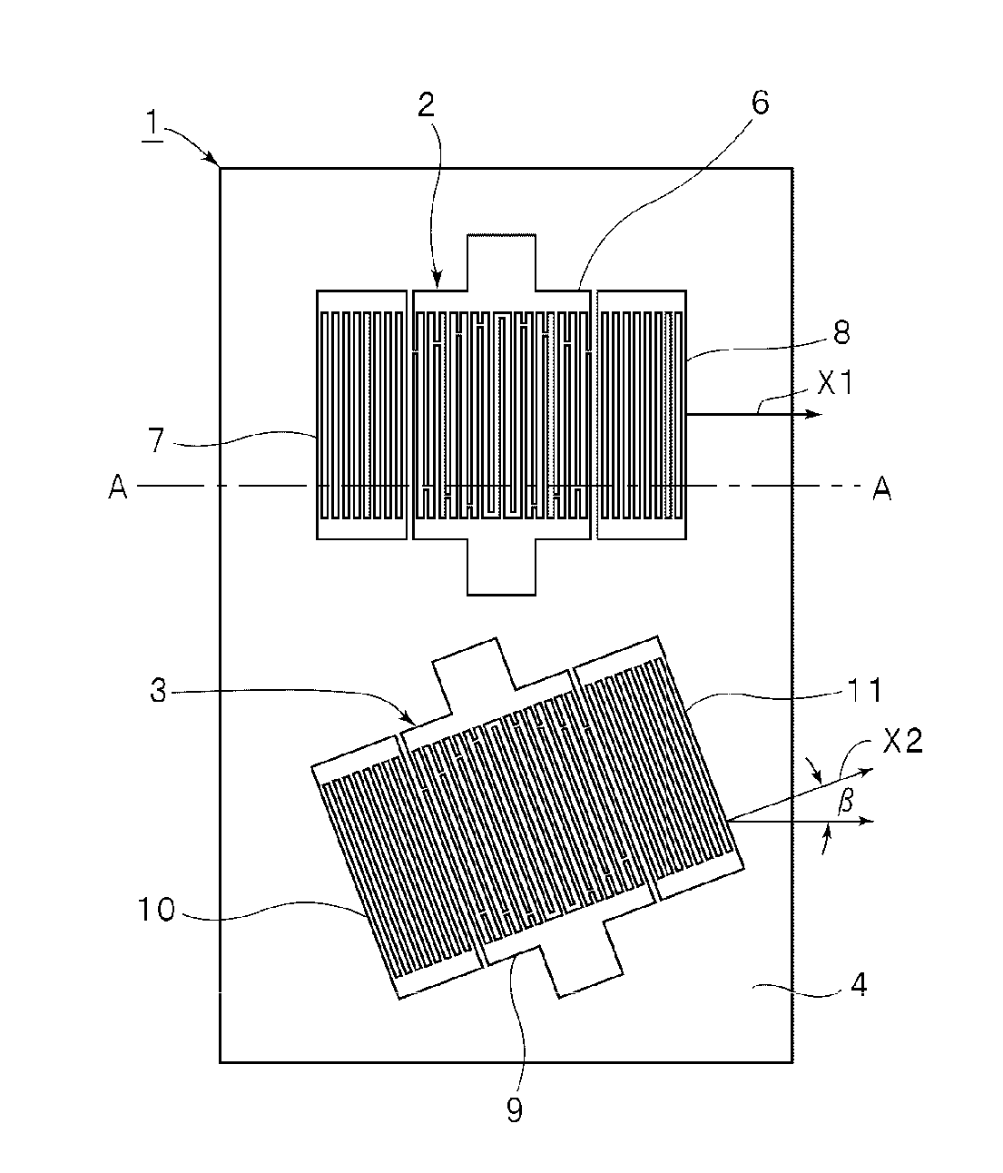
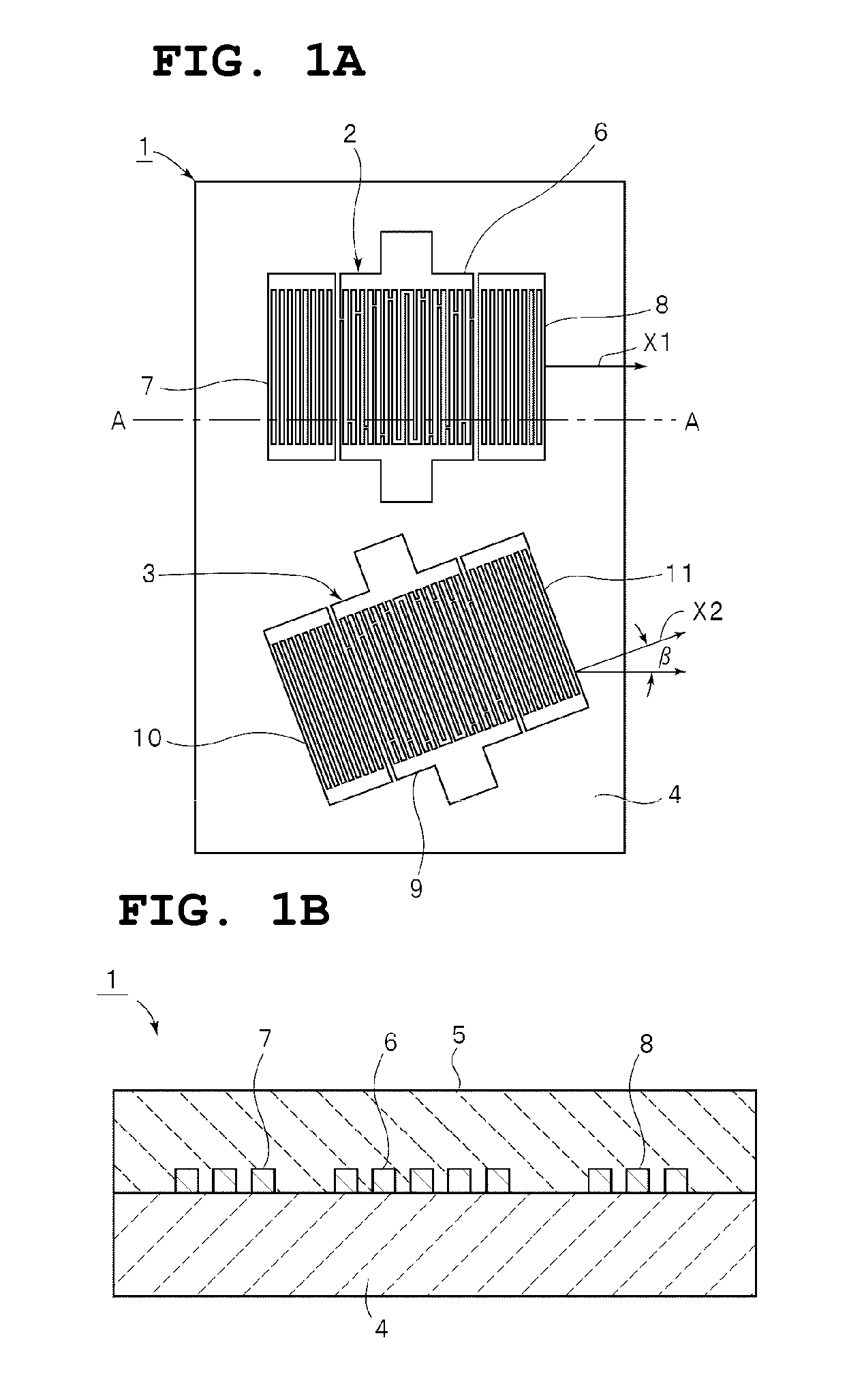
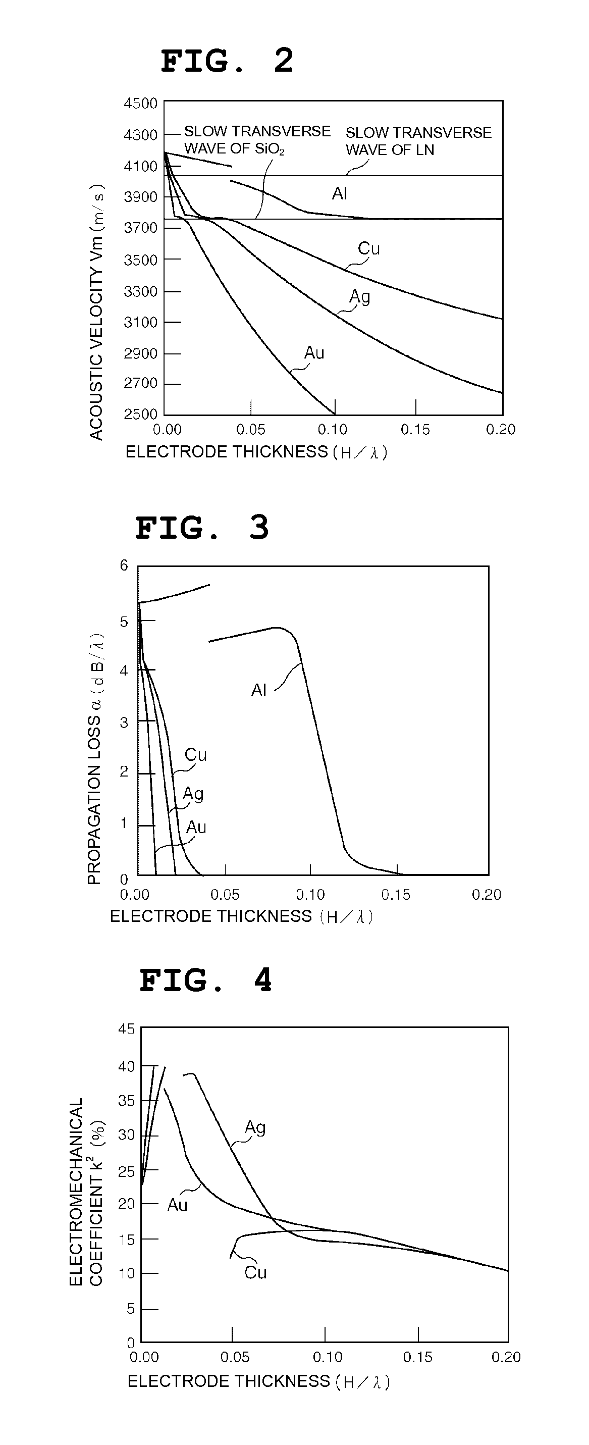
[0111] In the case in which electrodes were provided between a solid layer of SiO2 and a single crystal LiNbO3 substrate with Euler angles (0°, 90°, 0°) by using electrode materials having different densities, the relationships of an electrode thickness H / λ (in which H indicates the thickness, and λ indicates the wavelength of an SH type boundary acoustic wave) with the acoustic velocity, a propagation loss α, an electromechanical coefficient k2 (%), a temperature coefficient of frequency TCF (ppm / ° C.), and a power flow angle (PFA) of a boundary acoustic wave are shown in FIGS. 2 to 6, respectively.

[0112] The results shown in FIGS. 2 to 6 were obtained by calculation based on a method disclosed in “A Method For Estimating Optimal Cuts and Propagation Directions for Excitation and Propagation Directions for Excitation of Piezoelectric Surface Waves” (J. J. Campbell and W. R. Jones, IEEE Transactions on Sonics and Ultrasonics, Vol. SU-15 (1968) pp. 209 to 217).

[0113] In the case of...

experimental example 2

[0127] Based on the results obtained in Experimental Example 1, electrodes of Au having a thickness of 0.05 λ were provided on a LiNbO3 substrate with Euler angles (0°, θ, 0°), and a SiO2 film was provided so as to cover the electrodes of Au. In this structure, the relationships of θ of the Euler angles of the LiNbO3 substrate with the acoustic velocities V, the electromechanical coefficients k2, the propagation losses α, the temperature coefficients of frequency TCF, and the power flow angles (PFA) of an SH type boundary acoustic wave and a Stoneley wave were measured. FIGS. 9 to 11 show the relationships of the Euler angle θ with the acoustic velocity, the electromechanical coefficient k2, and the temperature coefficient of frequency TCF. In the entire region of θ=0° to 180°, the propagation loss α was 0 dB / λ and the power flow angle (PFA) was 0°.

[0128] In FIGS. 9 to 11, U2 indicates the SH type boundary acoustic wave, and U3 indicates the Stoneley wave which causes a spurious si...

experimental example 3

[0140] Next, electrodes of Au having a thickness of 0.06 λ were formed on respective LiNbO3 substrates with Euler angles (φ, 105°, 0°) and Euler angles (0°, 105°, ψ), and SiO2 films were formed to cover the electrodes of Au, so that boundary acoustic wave devices were provided. In this case, the relationships of the Euler angles θ and ψ of the LiNbO3 substrates with the acoustic velocities V, the electromechanical coefficients k2, the propagation losses α, the temperature coefficients of frequency TCF, and the power flow angles (PFA) of an SH type boundary acoustic wave (U2) and a Stoneley wave (U3) were measured. FIGS. 14 to 17 show the results obtained when the LiNbO3 with Euler angles (φ, 105°, 0°) was used, and FIGS. 18 to 21 show the results obtained when the LiNbO3 with Euler angles (0°, 105°, ψ) was used. In the entire region of φ of 0° to 90°, the propagation loss α is 0 dB / λ.

[0141] As apparent from FIG. 16, the electromechanical coefficient k2 of the Stoneley wave is small...


PUM


Abstract

A boundary acoustic wave device includes a solid layer laminated onto a single crystal substrate, electrodes provided between the single crystal substrate and the solid layer, and boundary acoustic wave elements provided on the single crystal substrate having the same cut angle, wherein the propagation direction of one of the boundary acoustic wave elements is different from that of at least one of the other boundary acoustic wave elements. A compact and high-performance boundary acoustic wave device using a boundary acoustic wave is provided by increasing the steepness of a filter band and by forming filters or resonators with different fractional bandwidths on a single substrate.

Description

FIELD OF THE INVENTION [0001] The present invention relates to a boundary acoustic wave device using a boundary acoustic wave, and more particularly, relates to a boundary acoustic wave device having a structure in which electrodes are disposed at a boundary between a single crystal substrate and a solid layer. DESCRIPTION OF THE RELATED ART [0002] Heretofore, various surface acoustic wave devices have been used for RF and IF filters in mobile phones, resonators in VCOs, VIF filters in televisions, and the like. Surface acoustic wave devices use a surface acoustic wave, such as a Rayleigh wave or a first leaky wave, which propagates along a surface of a medium. [0003] However, in propagating along a surface of a medium, a surface acoustic wave is sensitive to the changes in surface conditions of the medium. Accordingly, in order to protect the surface of the medium along which a surface acoustic wave propagates, a surface acoustic wave element has been hermetically sealed in a packa...

Claims


Application Information

Patent Timeline
Patent Type & Authority Applications(United States)
IPC IPC(8): H03H9/64H03H9/02H03H9/145H03H9/25
CPCH03H9/0222H03H9/02559H03H9/14538H03H9/6483H03H9/145H03H9/25
Inventor KANDO, HAJIME
Owner MURATA MFG CO LTD
Why Eureka
Try Eureka