Eureka AIR delivers breakthrough ideas for toughest innovation challenges, trusted by R&D personnel around the world.

Method and Circuit for Driving a Gas Discharge Lamp

a technology of gas discharge lamp and circuit, which is applied in the direction of electric variable regulation, process and machine control, instruments, etc., can solve the problems of current change, in particular, visible flickering of lamps, and achieve the effect of high ignition voltag

Active Publication Date: 2008-12-11
LUMILEDS
View PDF6 Cites 0 Cited by
  • Summary
  • Abstract
  • Description
  • Claims
  • Application Information

AI Technical Summary

Benefits of technology

[0011]In an embodiment, the reversal voltage generation circuit is a resonant circuit connected to an output of the current source. A suitable resonant circuit is designed and configured to generate a relatively high voltage is response to an instantaneous polarity transition of a voltage supplied to the resonant circuit, i.e. the voltage supplied by the current source. It is noted that in the prior art, e.g. from U.S. Pat. No. 6,124,682, it is known to provide addition

Problems solved by technology

Due to the relatively small voltage difference and the inductance of the ignition circuit between the driver circuit and the lamp, a current change, in particular after the current

Method used


Image

  • Method and Circuit for Driving a Gas Discharge Lamp
  • Method and Circuit for Driving a Gas Discharge Lamp

Examples


Embodiment Construction

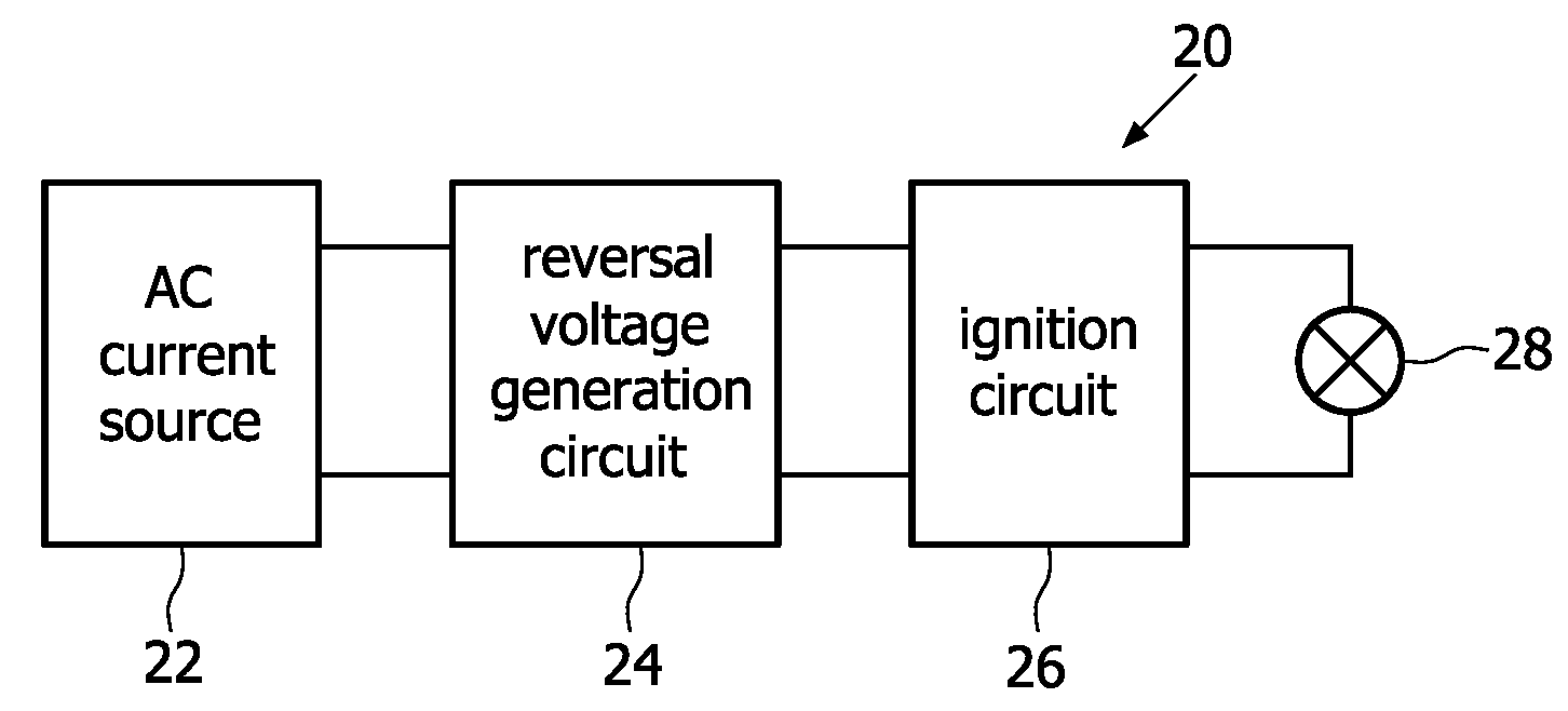
[0017]FIG. 1 shows a graph of a lamp driver voltage 1, a lamp voltage 2 and a lamp current 3 (vertical axis) as a function of time t (horizontal axis). The lamp driver voltage 1, the lamp voltage 2 and the lamp current 3 have been measured on a prior art lamp driver circuit coupled to a gas discharge lamp, in particular an automotive xenon lamp.

[0018]In a stable operating period t0−t1, the lamp driver voltage 1 is at a negative operating voltage level −Vop. The lamp voltage 2 is substantially equal to the lamp driver voltage 1. The lamp current 3 is at a stable operating current level −Iop.

[0019]At time t1 the lamp driver voltage 1 is changed from a negative operating voltage level −Vop to a positive operating voltage level Vop virtually instantaneously. As a result, the lamp voltage 2 and the lamp current 3 start to change as well, but due to impedance in the circuitry, the lamp voltage 2 and the lamp current 3 change gradually. In a period t1−t2 the (absolute) lamp voltage 2 and t...


PUM


Abstract

The invention relates to a method for driving a gas discharge lamp and relates to a lamp driver circuit for driving a gas discharge lamp in accordance with said method. The method comprises supplying a current to the gas discharge lamp, reversing the direction of the current supplied to the gas discharge lamp and, substantially simultaneously, generating a relatively high voltage. The generated high voltage serves to prevent a series of re-ignitions of the gas discharge lamp that may lead to visible flickering of the gas discharge lamp or to extinction of the gas discharge lamp.

Description

FIELD OF THE INVENTION[0001]The invention relates to a method and a circuit for driving a gas discharge lamp.BACKGROUND OF THE INVENTION[0002]In a known method for driving a gas discharge lamp, e.g. an automotive xenon lamp, an alternating current is supplied to the gas discharge lamp. For example, a square wave current of a frequency of about 400 Hz is generated in a lamp driver circuit. The lamp driver circuit may comprise a direct current source and a commutation circuit for converting a direct current into an alternating current. Further, an ignition circuit may be provided for igniting the lamp. The ignition circuit may comprise a pulse transformer to supply a desired voltage pulse for igniting the lamp.[0003]In a known system comprising a driver circuit, an ignition circuit and a gas discharge lamp, it was observed that relatively short interruptions in the current occurred substantially immediately after a reversal of a direction of the current, in particular immediately afte...

Claims


Application Information

Patent Timeline
IPC IPC(8): H05B41/36
CPCH05B41/2883H05B41/2928Y02B20/204Y02B20/208Y02B20/00
Inventor LUERKENS, PETER
Owner LUMILEDS
Why Eureka
Eureka Blog
Learn More