Eureka AIR delivers breakthrough ideas for toughest innovation challenges, trusted by R&D personnel around the world.

Method for igniting high-pressure discharge lamps

A technology of high-pressure discharge lamps and igniters, which is applied in the use of gas discharge lamps, electric light sources, electrical components, etc., and can solve the problem that the ignition of high-pressure discharge lamps is not optimal

Inactive Publication Date: 2015-08-26
OSRAM GMBH
View PDF4 Cites 0 Cited by
  • Summary
  • Abstract
  • Description
  • Claims
  • Application Information

AI Technical Summary

Problems solved by technology

[0005] However, the resulting ignition pulse shape is not optimal for igniting high-pressure discharge lamps

Method used


Image

  • Method for igniting high-pressure discharge lamps
  • Method for igniting high-pressure discharge lamps
  • Method for igniting high-pressure discharge lamps

Examples


Embodiment Construction

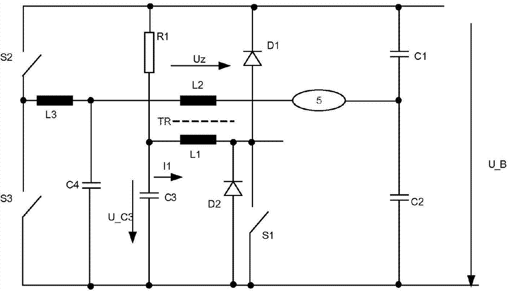
[0037] figure 1 A circuit arrangement known per se for operating a high-pressure discharge lamp is shown, said circuit arrangement having a half-bridge with series-connected half-bridge switches S2 and S3, at the center point of which a lamp choke is connected The series circuit of coil L3, secondary coil L2 of transformer TR and high-pressure discharge lamp 5 is ignited. The free end of the high-pressure discharge lamp 5 is connected to the connection point of the series circuit of two coupling capacitors C1 and C2. The half-bridge is connected in parallel with a series circuit of coupling capacitors. A supply voltage U_B (425 V in this exemplary embodiment) is applied to the parallel circuit. The ignition capacitor C3 and the ignition switch S1 are connected in series with the freewheeling diode D2 connected in parallel to the primary coil L1, which forms a primary circuit. The anode of the freewheeling diode and one terminal of the ignition capacitor C3 are connected to ...


PUM


Abstract

A method for starting a high-pressure discharge lamp by means of a starter, having a starting capacitor, a starting switch and a starting transformer, wherein the method comprises the following temporally successive steps: charging the starting capacitor to a predetermined voltage; closing the starting switch; and opening the starting switch before the current through the starting switch reaches zero for the first time in terms of its fundamental component.

Description

technical field [0001] The invention relates to a method for igniting a high-pressure discharge lamp by means of a igniter. Background technique [0002] The invention is based on a method for igniting a high-pressure discharge lamp by means of an igniter with an ignition transformer according to the independent claims. [0003] Such an igniter and an ignition method are known from DE19909529A1. The known igniter has an ignition transformer, an ignition capacitor and a spark gap as an ignition switch. The primary coil is in series with the ignition capacitor and with the spark gap. The secondary coil is connected into the current path of the high-pressure discharge lamp to be ignited. A charging voltage is applied in parallel with the ignition capacitor. If the charging voltage exceeds the switching voltage of the spark gap, the spark gap is switched on and a brief, high current pulse occurs in the primary winding of the ignition transformer, which is step-up converted a...

Claims


Application Information

Patent Timeline
Patent Type & Authority Patents(China)
IPC IPC(8): H02M1/00H05B41/288
CPCH05B41/2881H05B41/04Y02B20/204Y02B20/00H05B41/18H05B41/24H05B41/288
Inventor 约阿希姆·米尔施勒格尔
Owner OSRAM GMBH
Why Eureka
Eureka Blog
Learn More