Mirror angle transducer and mirror tilting mechanism

Inactive Publication Date: 2005-10-13
MURAKAMI CORP
View PDF13 Cites 19 Cited by
  • Summary
  • Abstract
  • Description
  • Claims
  • Application Information

AI Technical Summary

Benefits of technology

[0014] For such a coupling means, a combination of projections formed in an element of the sliding mechanism and holes made in the sliding contactor provides a stable contact between the electrical contactor and the resistor strip. As the result, a stable and reproducible positioning of the electrical contactor on the resistor strip is obtained.
[0015] For such a coupling means, a combination of through holes formed in an element of the sliding mechanism, clip holes made in the sliding contactor and clips that are set through the through holes and clip holes provides a stable contact between the sliding contactor and the resistor strip. As the result, a stable and reproducible positioning of the electrical contactor on the resistor strip is obtained.
[0016] For such a coupling means, a combination of through holes formed in an element of the sliding mechanism, rivet holes made in the sliding contactor and rivets that are set through the through holes and rivet holes provides a stable contact between the sliding contactor and the resistor strip. As the result, a stable and reproducible positioning of the electrical contactor on the resistor strip is obta

Problems solved by technology

It is weary to adjust the mirror angle every time the driver to garage the vehicle.
In other words, the twist force provides in-ti

Method used


Image

  • Mirror angle transducer and mirror tilting mechanism
  • Mirror angle transducer and mirror tilting mechanism
  • Mirror angle transducer and mirror tilting mechanism

Examples


Example

(First Embodiment)

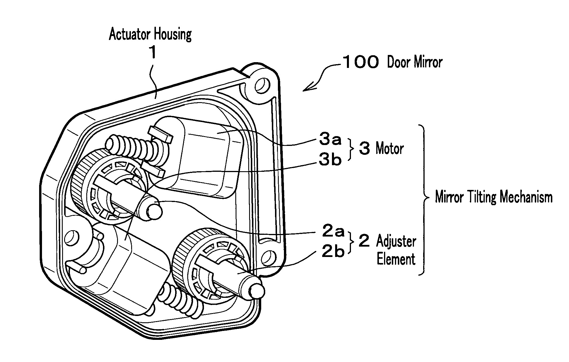
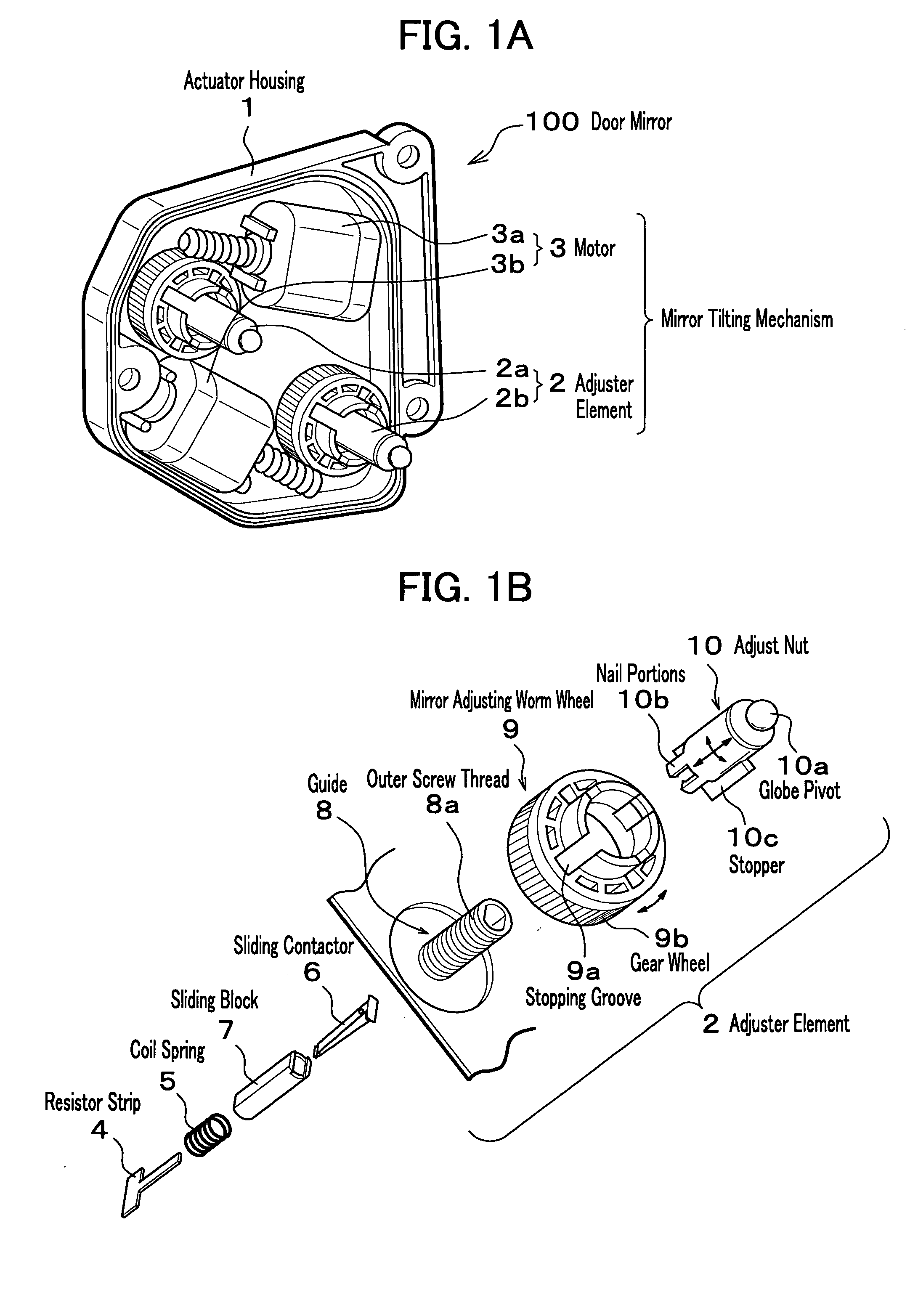
[0036] The first embodiment of the present invention is shown in FIG. 1A and FIG. 1B.

[0037]FIG. 1A is a schematic that shows an actuator used for the mirror angle adjustment for which the mirror angle transducer is used. The door mirror 100 is composed of the actuator to which the mirror angle transducer is used as shown in FIG. 1A. The mirror tilting mechanism is assembled in the actuator housing. The mirror tilting mechanism is composed of two sets of an adjuster element 2 (actually 2a or 2b), a motor 3 (actually 3a or 3b) with a worm set in the motor shaft. The detail assembly of the adjuster element 2a or 2b is shown in FIG. 1B.

[0038] There are two adjuster elements 2a and 2b used for the mirror tilting mechanism 2 constructed in the actuator housing 1. The adjuster elements 2a and 2b are driven by two motors 3a and 3b with worms, respectively and can tilt the mirror in the vertical plane and the horizontal plane.

[0039] The adjuster element 2b, for example...

Example

(Second Embodiment)

[0053]FIG. 5B shows the second embodiment of the present invention. The difference from the first embodiment of which details are shown in FIG. 5A is that a pair of clip holes 16a, a pair of through holes 17a and a pair of clips 18 are used to make mechanical tightness between the sliding contactor 16 and the sliding block 17.

[0054] One clip 18 is inserted into one through hole 17a made in the sliding block 17 and one clip hole 16a made in the sliding contactor 16. The other clip 18 is inserted into the other through hole 17a made in the sliding block 17 and the other clip hole 16a made in the sliding contactor 16. The tips of the clips 18 become wider than the diameter of the clip holes 16a and hardly drop off from the clip holes 16a. The clips 18 make the sliding contactor 16 latched to be fixed to the sliding block 17. This latch mechanism keeps the complete stability against the rotational friction to the adjust nut 10 which mechanically contacts to the sli...

Example

(Third Embodiment)

[0056]FIG. 5C shows the third embodiment of the present invention. The difference from the first embodiment is that a pair of rivet holes 26a, a pair of through holes 27a and a pair of rivets 28 are used to make mechanical tightness between the sliding contactor 26 and the sliding block 27.

[0057] One rivet 28 is inserted into one through hole 27a made in the sliding block 27 and one rivet hole 26a made in the sliding contactor 26. The other rivet 28 is inserted into the other through hole 27a made in the sliding block 27 and the other rivet hole 26a made in the sliding contactor 26. By using a special tool, the tips of the rivets 28 are pressed to be wider than the diameter of the rivet holes 26a and hardly drop off from the clip holes 26a. The rivets 28 stake the sliding contactor 16 to be fixed to the sliding block 27. This stake mechanism keeps the complete stability against the rotational friction to the adjust nut 10 which mechanically contact to the slidin...


PUM


Abstract

A mirror angle transducer that detects tilting angles of a mirror applied to vehicles, wherein the tiling angle is adjusted by an adjuster element installed in an actuator housing, comprises a guide that has a non-circular hollow and composes the adjuster element, a sliding block that has a hole and is inserted into the non-circular hollow of the guide, a resistor strip that has a resistive layer and a conductive strip layer on one surface and the other surface, respectively and is set in the hole of the sliding block, a sliding contactor that makes electrical contact with the resistor by pinching and sliding on the surfaces of the resistor strip, and a coupling means that provides mechanically tight combining of the sliding contactor to the sliding block so that a stable and reproducible positioning of the electrical contactor on the resistor strip is obtained.

Description

CROSS-REFERENCE TO RELATED APPLICATION [0001] The disclosure of Japanese Patent Application No. 2004-113183 filed on Apr. 7, 2004 including the specification, drawings and abstract is incorporated herein by reference in its entirety. FIELD OF THE INVENTION [0002] The present invention relates to a transducer to detect the tilt angle of mirrors used for various vehicles so that the sight angle of the mirrors can be adjusted by remote controlling technologies and a mechanism that works in corporation with the transducer in a configuration of an actuator for the mirror. BACKGROUND OF THE INVENTION [0003] As for the mirror used for the vehicles, it is necessary to change the sight angle of the mirror in accordance with the attitude of the driver for safety reasons. Since it is a nuisance to handle or manipulate the mirror and adjust the sight angle of the mirror, remote manipulations of the mirrors by which the sight angles can be adjusted are generally used now-a-day. As for the mechan...

Claims


Application Information

Patent Timeline
IPC IPC(8): B60R1/072G02B7/182
CPCB60R1/072
Inventor YAMADA, AYAKO
Owner MURAKAMI CORP
Why Eureka
Try Eureka