
Clutch based on air conveying system device

A transmission system and clutch technology, applied in the field of clutches, to achieve the effect of convenient control

Active Publication Date: 2017-08-22
TIANJIN JINHANG COMP TECH RES INST
View PDF11 Cites 0 Cited by
  • Summary
  • Abstract
  • Description
  • Claims
  • Application Information

AI Technical Summary

Problems solved by technology

[0006] The purpose of the present invention is to provide a clutch based on the wind conveying system device, through which the existing problems are solved

Method used


Image

  • Clutch based on air conveying system device
  • Clutch based on air conveying system device

Examples


Embodiment Construction

[0024] The following will clearly and completely describe the technical solutions in the embodiments of the present invention with reference to the accompanying drawings in the embodiments of the present invention. Obviously, the described embodiments are only some, not all, embodiments of the present invention. Based on the embodiments of the present invention, all other embodiments obtained by persons of ordinary skill in the art without creative efforts fall within the protection scope of the present invention.

[0025] In describing the present invention, it is to be understood that the terms "opening", "upper", "lower", "thickness", "top", "middle", "length", "inner", "surrounding" etc. Indicating orientation or positional relationship is only for the convenience of describing the present invention and simplifying the description, and does not indicate or imply that the components or elements referred to must have a specific orientation, be constructed and operated in a sp...


PUM


Abstract

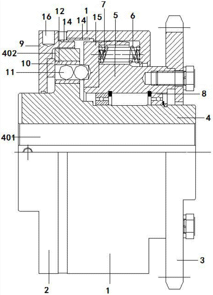
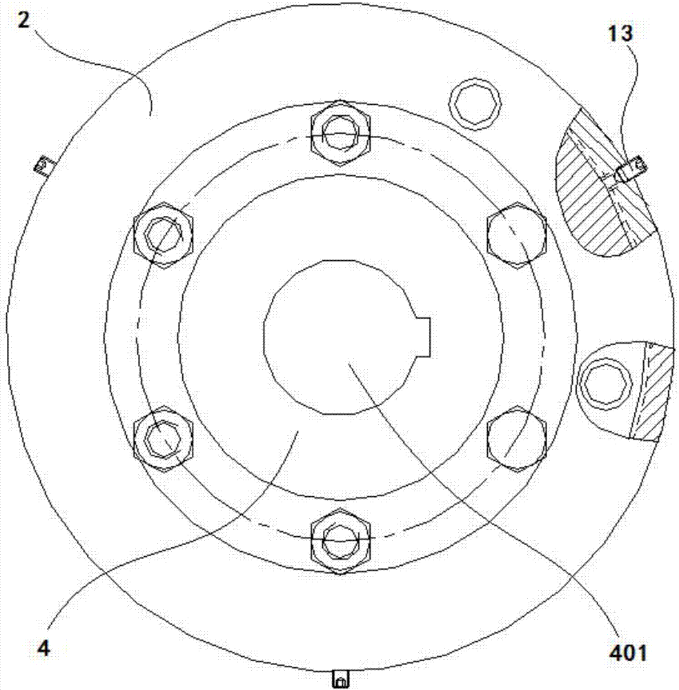
The invention discloses a clutch based on an air conveying system device. The clutch comprises a drive disc hub. One end of the drive disc hub is provided with a driven disc hub in a matched mode, and the other end of the drive disc hub is provided with a first clutch disc in a matched mode; a cutting disc is arranged in the middle of the circumferential side of the drive disc hub; through holes are formed in one end surface of the cutting disc in an evenly-distributed mode in the circumferential direction, a sleeve is embedded into each through hole, and the sleeve is internally provided with metal balls in the matched mode; a second clutch disc is arranged on the circumferential side of the driven disc hub in the matched mode; and a gear disc is fixed to one end surface of the driven disc hub. According to the clutch based on the air conveying system device, power transmitting is conducted through two friction cylinders capable of being separated from each other, and the contact mode is safe, efficient, stable and convenient to control; and the reciprocating action of the friction cylinders is conducted through double springs, cutting of two blocking discs is conducted through the multiple metal balls, and rolling friction of the blocking discs and the metal balls is achieved.

Description

technical field [0001] The invention belongs to the technical field of clutches, in particular to a clutch based on a wind conveying system device. Background technique [0002] The clutch is installed between the engine and the transmission, and is an assembly directly connected with the engine in the car drive train. Usually, the clutch is installed together with the flywheel set of the engine crankshaft, which is the part that cuts off and transmits power between the engine and the vehicle transmission system. During the whole process of the car from starting to normal driving, the driver can manipulate the clutch as needed to temporarily separate or gradually engage the engine and drive train to cut off or transfer the power output from the engine to the drive train. Its function is to make the engine and the transmission gradually engage, so as to ensure the smooth start of the car; temporarily cut off the connection between the engine and the transmission, so as to fa...

Claims


Application Information

Patent Timeline
Patent Type & Authority Applications(China)
IPC IPC(8): F16D13/70F16D13/60F16D13/64F16D13/58
CPCF16D13/58F16D13/60F16D13/64F16D13/70
Inventor 张燕
Owner TIANJIN JINHANG COMP TECH RES INST
Learn More