a drum brake

A drum brake and brake technology, which is applied in the direction of drum brakes, brake types, brake parts, etc., can solve the problems of increasing the contact area of ​​sliding friction, inconvenient loading and unloading, and many parts required

Active Publication Date: 2016-04-06
朱启东
View PDF5 Cites 0 Cited by
  • Summary
  • Abstract
  • Description
  • Claims
  • Application Information

AI Technical Summary

Problems solved by technology

However, in the prior art, the above-mentioned friction is mostly sliding friction formed between narrow planes, so not only is there excessive wear and tear, which shortens the overall service life of the drum brake, but also causes the driving brake to be damaged due to the large friction coefficient of sliding friction. The driving force of the camshaft rotation also increases, resulting in a greater force required for braking
[0004] In the prior art, there are also related documents that propose to improve the above-mentioned sliding friction, thereby effectively reducing wear and braking driving force, but in these patents, the corresponding rolling friction or increased sliding friction is achieved through the cooperation of multiple components. The contact area generally has problems such as complicated structure and inconvenient loading and unloading. For example, in the CN201110263455.9 patent, it first puts a brake wheel on the rectangular block, and then opens several grooves on the outer surface of the brake wheel. The rollers roll along the grooves on the outer surface of the brake wheel to realize the rolling friction between the rollers and the brake shoe. Since the rollers and the brake wheel are relatively rolling, several limit structures need to be set accordingly To effectively limit the rolling track of the roller, the structure is very complicated, many parts are required, and the production cost is high. At the same time, the parts need to be installed together, so there are still problems such as inconvenient loading and unloading.

Method used


Image

  • a drum brake
  • a drum brake
  • a drum brake

Examples


Embodiment Construction

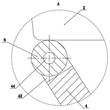
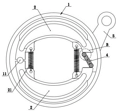
[0025] Such as figure 1 , 2 , 3, 4, 5, 6, 7, 8, 9, 10, and 11 show a drum brake, including a housing 1, a brake camshaft 3 and two brake shoes placed in the housing 1 2. The outer end of the brake camshaft 3 located outside the housing 1 is in transmission connection with the brake arm 5 that drives it to rotate. Formed rectangular block 4, the two long sides 43 and the two short sides 41 of the rectangular block 4 can be a traditional planar structure, and certainly can be an arc structure, between the long side 43 and the short side 41 The arc surface transition connection is preferred. The two brake shoes 2 are symmetrically arranged, and the housing 1 is provided with a boss 11, and one end of the two brake shoes 2 forms a hinged rotation fit with the boss 11, and the other end of the two brake shoes 2 is an expansion brake. end, the rectangular block 4 is located between the expansion brake ends of the two brake shoes 2, and a return tension spring 21 is also provided ...


PUM


Abstract

The invention discloses a drum brake which comprises a shell, a brake cam shaft and two brake shoes, wherein the two brake shoes are arranged in the shell; the outer end, which is positioned outside the shell, of the brake cam shaft is in driving connection with a brake arm which drives the brake cam shaft to rotate; the inner end, which is positioned inside the shell, of the brake cam shaft is provided with a rectangular block which is defined by two long edges and two short edges; certain ends of the two brake shoes are articulated with the shell, and the other ends of the two brake shoes are expansion brake ends; the rectangular block is positioned between the expansion brake ends of the two brake shoes; the side surfaces of two short edges of the rectangular block are respectively provided with one groove; two sides of the grooves respectively penetrate through the side surfaces of two long edges of the rectangular block; rolling pieces which form rolling friction with the corresponding end surfaces of the brake shoes are movably arranged in the grooves. According to the adopted structure, rolling friction is adopted, so that abrasion can be effectively reduced, and the brake driving force is correspondingly and greatly reduced; furthermore, the rolling pieces capable of realizing rolling friction are simple in structure and convenient to assemble and disassemble.

Description

technical field [0001] The invention relates to a drum brake and belongs to the field of vehicle braking devices. Background technique [0002] Drum brakes are commonly used braking devices for existing vehicles. In the prior art, drum brakes usually include a housing, a brake camshaft and two brake shoes placed in the housing. The brake camshaft is located at the outer end of the housing. It is connected with the brake arm that drives its rotation. The inner end of the brake camshaft located in the housing is provided with a rectangular block surrounded by two long sides and two short sides. The two brake shoes are arranged symmetrically. One end is hinged on the housing, and the other end of the two brake shoes is an expansion brake end. The rectangular block is located between the expansion brake ends of the two brake shoes, and a return tension spring is arranged between the two brake shoes. [0003] Under normal conditions, under the action of the return tension spring...

Claims


Application Information

Patent Timeline
Patent Type & Authority Patents(China)
IPC IPC(8): F16D51/18F16D65/04
Inventor 朱启东
Owner 朱启东
Why Eureka
Try Eureka