Magnetic energy boosting machine

A booster and magnetic energy technology, applied in the direction of generators/motors, electrical components, etc., can solve problems such as unreasonable configuration of engines, and achieve the effects of reducing energy consumption, saving energy, and reducing configuration power

Inactive Publication Date: 2009-07-08
HEBEI GUANGDE SHENGJIYONG MAGNETIC LEVITATION POWER MACHINERY EXPLOITURE
View PDF0 Cites 0 Cited by
  • Summary
  • Abstract
  • Description
  • Claims
  • Application Information

AI Technical Summary

Problems solved by technology

[0003] The purpose of the present invention is to provide a magnetic energy booster as an engine auxiliary booster to solve the prob

Method used


Image

  • Magnetic energy boosting machine
  • Magnetic energy boosting machine

Examples


Embodiment Construction

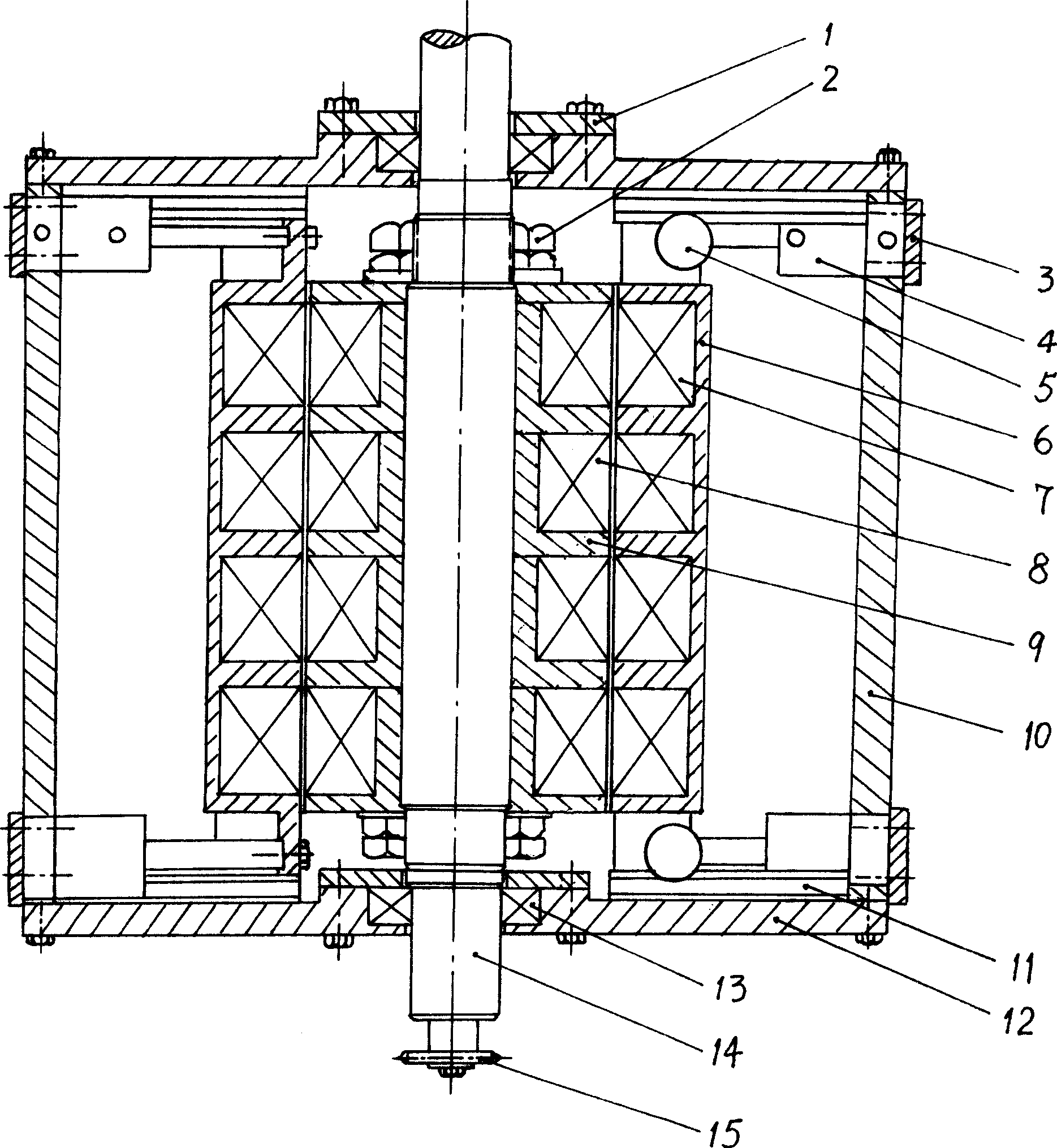
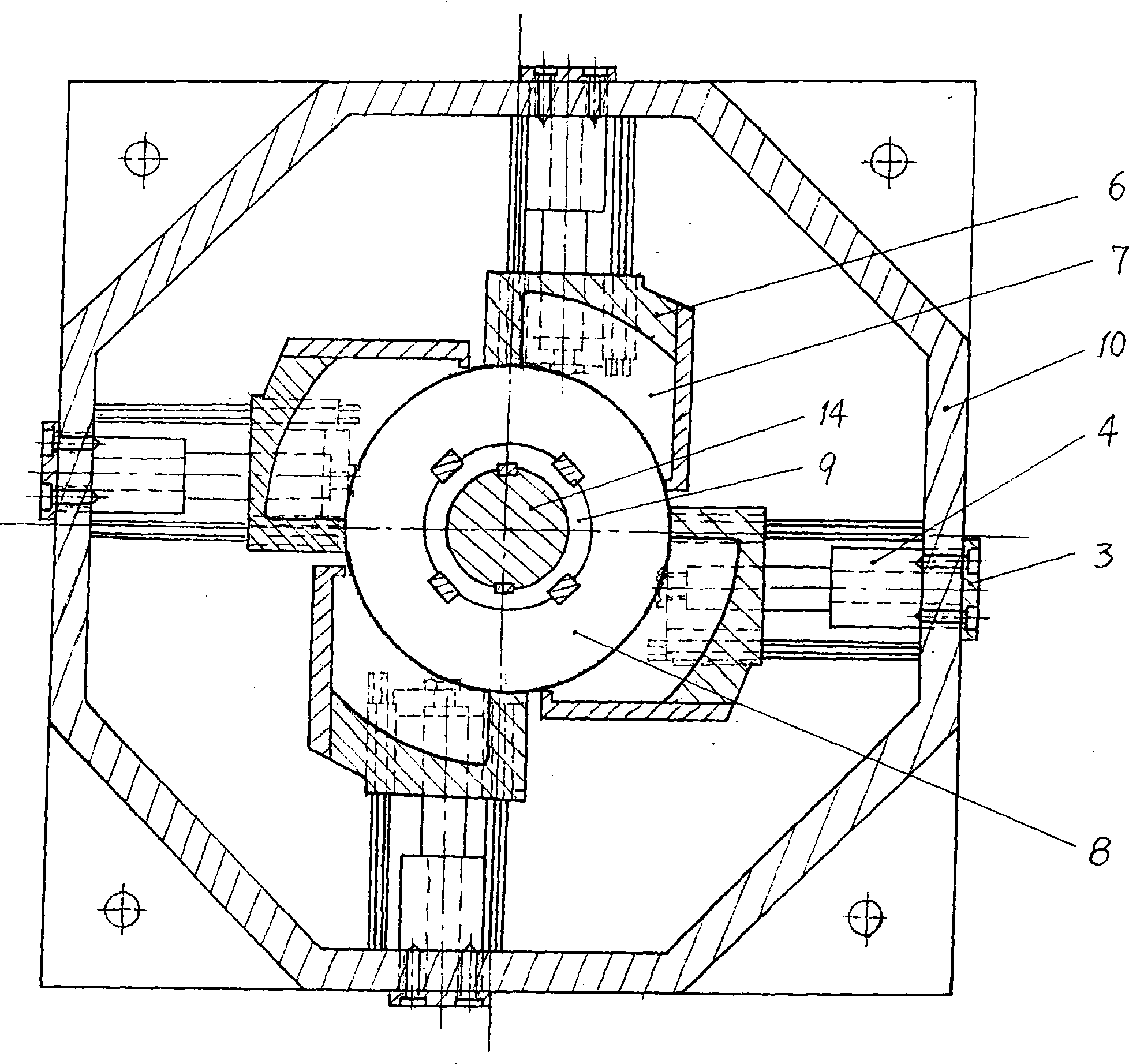
[0013] Such as figure 1 As shown, the box body 10 is a regular octagonal cylindrical shell, and the upper and lower ports of the box body 10 are respectively connected with end caps 12 . The main shaft 14 is supported by bearings 13 in the central holes of the upper and lower end covers. A bearing cover 1 is sealed on the bearing port. The lower end of the main shaft 14 is connected with a transmission mechanism 15 that drives the main shaft to rotate; in the middle of the main shaft 14, there is a four-layer magnetic ring seat 9 made of a magnetic isolation material, and four magnetic rings spaced apart from each other are housed in the magnetic ring seat 9. Ring 8; upper and lower nuts 2 are screwed on the main shaft 14 to fix the magnetic ring seat 9 in the middle.

[0014] The magnetic push mechanism includes parts such as cylinder 4, magnetic block seat 6 and magnetic block 7. Every cover magnetic push mechanism can have one to two cylinders 4. figure 1 There are uppe...


PUM


Abstract

The invention relates to a magnetic energy boosting machine, which has the structure that an electric motor or an actuating mechanism for driving a work spindle to rotate is connected with the work spindle; the work spindle is supported on end housings through a bearing; the two end housings are connected with the upper end and the lower end of a box body in a sealing manner; a magnetic ring seat is fixed at the middle part of the magnetic ring; a magnetic ring is arranged in the magnetic ring seat; a magnetic pushing mechanism is arranged in the box body; in the magnetic pushing mechanism, a magnetic block seat is connected with the front end of a cylinder piston rod, and a magnetic block is arranged in the magnetic block seat; and the magnetic block is opposite to the magnetic ring on the same layer on the work spindle flush, and adjacent surfaces of the magnetic block and the magnetic ring have the same polarity. The magnetic energy reinforcement machine is used as an auxiliary booster, and reduces the allocating power of an engine after being applied, thereby solving the problem that the engine is allocated unreasonably in vehicles and engineering machinery, realizing energy conservation, and reducing energy consumption.

Description

technical field [0001] The invention relates to a mechanical power device, in particular to a magnetic energy booster. technical background [0002] In many workplaces or working devices, it is often necessary to provide relatively large power in a short period of time to complete a certain work task, such as starting a vehicle, starting a construction machine with a load, and so on. At this time, the output torque of the engine is required to be several times or even ten times higher than the normal working torque. In order to meet the working needs of this short-term high-torque output of the engine, the current solution is to only configure a high-power engine. Although the configuration of this high-power engine meets the working requirements of short-term high-torque output, the configuration and use of this high-power engine under the long-term normal working torque output requirements will inevitably form a "big The situation of "horse-drawn trolley", the excessive ...

Claims


Application Information

Patent Timeline
IPC IPC(8): H02N11/00
Inventor 刘明李静
Owner HEBEI GUANGDE SHENGJIYONG MAGNETIC LEVITATION POWER MACHINERY EXPLOITURE
Why Eureka
Try Eureka