
Power supplying device for mechanical equipment and method for reducing configuration power of mechanical equipment

A technology for mechanical equipment and power reserve, applied in sequence/logic controller program control, electrical program control and other directions, can solve the problems of mechanical equipment configuration power damage, no early warning of mechanical equipment failure or damage, power waste and other problems

Inactive Publication Date: 2012-03-21
孙明昭
View PDF0 Cites 0 Cited by
  • Summary
  • Abstract
  • Description
  • Claims
  • Application Information

AI Technical Summary

Problems solved by technology

In order to ensure the reliable operation of mechanical equipment, when selecting and setting the configured power, the configured power is usually set in consideration of the unpredictable increase in resistance and increased load caused by pollution, damage, or wear of the mechanical equipment. The configured power is much greater than the actual power required to drive the mechanical equipment, so usually most of the configured power exceeds the driving power actually required by the mechanical equipment by 1 time or more, so the above-mentioned load increase does not occur on the mechanical equipment When , most of the configured power of the driving mechanical equipment is wasted
[0003] At the same time, when the mechanical equipment suffers from pollution damage, or wear and other unpredictable resistance increases, resulting in increased load, setting a smaller configuration power is likely to cause damage to the configuration power of the mechanical equipment, and there is no early warning system to inform all Early failure or damage of the above-mentioned mechanical equipment

Method used

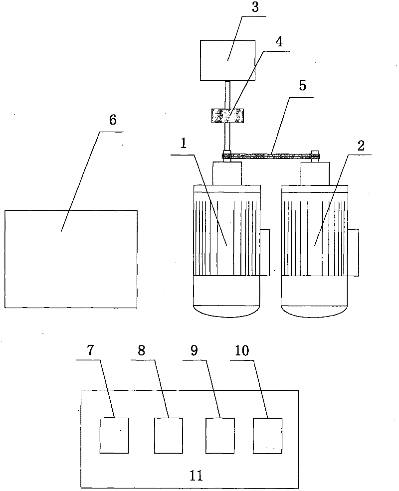
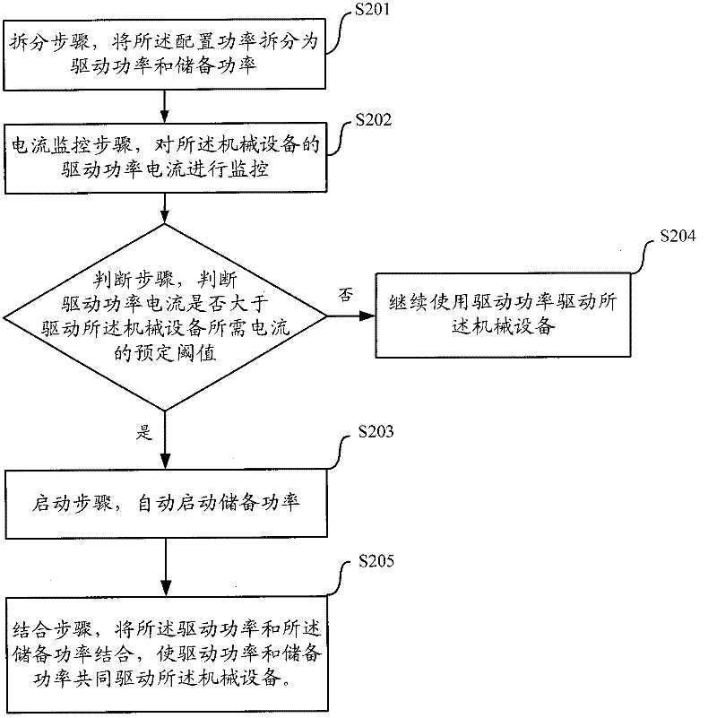
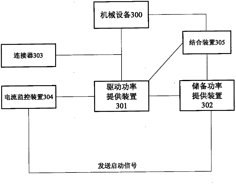

Image

  • Power supplying device for mechanical equipment and method for reducing configuration power of mechanical equipment
  • Power supplying device for mechanical equipment and method for reducing configuration power of mechanical equipment
  • Power supplying device for mechanical equipment and method for reducing configuration power of mechanical equipment

Examples


Embodiment Construction

[0031] The following will refer to the attached Figure 1-3 The present invention is further described in detail.

[0032] figure 1 It is a schematic diagram of the hardware connection structure of a power supply device of a mechanical device according to a preferred embodiment of the present invention. Such as figure 1 As shown, the reference numerals in the figure represent respectively as follows:

[0033] 1. Drive power supply device 2. Reserve power supply device

[0034] 3. Mechanical equipment 4. Connectors

[0035] 5. Combined device 6. Control box

[0036] 7. Driving power ammeter 8. Current monitoring device

[0037] 9. Alarm device 10. Reserve power ammeter

[0038] 11. Electrical instrument box

[0039] Wherein, the driving power supply device 1 is used to provide the mechanical equipment 3 with the driving power required to drive the mechanical equipment 3, the driving power here is different from the traditional driving power, and the setting of the tradi...


PUM


Abstract

The invention discloses a power supplying device for mechanical equipment, which comprises a driving power supply device and a reserved power supply device, wherein the driving power supply device and the reserved power supply device are respectively used for providing driving power and reserved power. The power supplying device for the mechanical equipment is characterized by comprising a connector, a current monitoring device and a combined device, wherein the connector is used for connecting the mechanical equipment and the driving power supply device; the current monitoring device is used for monitoring driving power current provided in the driving power supply device; when the driving power current is more than the preset threshold value of the required current of the mechanical equipment, a starting signal is sent to the reserved power supply device, and the reserved power supply device is started; the combined device is used for combining power provided by the driving power supply device and the power provided by the reserved power supply device; and the combined power is provided and used for mutually driving the mechanical equipment. The invention also discloses a method for reducing the configuration power of the mechanical equipment. According to the device and the method, the use ratio of the configuration power of the mechanical equipment is optimized to the maximum extent, and the early-stage fault of the equipment can be processed.

Description

technical field [0001] The present invention relates to the field of allocation of configuration power in mechanical equipment, and more particularly, the invention relates to a power supply device for mechanical equipment and a method for reducing the configuration power of mechanical equipment. Background technique [0002] The operation of traditional mechanical equipment is driven by configuring power. In order to ensure the reliable operation of mechanical equipment, when selecting and setting the configuration power, the configuration power is usually set in consideration of the increase in load caused by unpredictable resistance such as pollution damage or wear of the mechanical equipment. The configured power is much greater than the actual power required to drive the mechanical equipment, so usually most of the configured power exceeds the driving power actually required by the mechanical equipment by 1 time or more, so the above-mentioned load increase does not occ...

Claims


Application Information

Patent Timeline
IPC IPC(8): G05B19/04
Inventor 孙明昭
Owner 孙明昭
Learn More