Lifting upright post with rolling assemblies

A technology of lifting columns and rolling parts, which is applied to the connection of rods, connecting components, mechanical equipment, etc., which can solve the problems of unsmooth lifting of the inner tube, jamming, and increased resistance of the inner tube, so as to achieve simple structure and prevent mutual wear , the effect of prolonging the service life

Pending Publication Date: 2019-08-06
ZHEJIANG JIECHANG LINEAR MOTION TECH
View PDF0 Cites 0 Cited by
  • Summary
  • Abstract
  • Description
  • Claims
  • Application Information

AI Technical Summary

Problems solved by technology

[0002] At present, the lifting column has been widely used. During the lifting process of the lifting column, the friction plate between the inner tube and the outer tube can prevent the inner tube from shaking. However, the friction plate increases the force on the inner tube during the lifting process. The resistance makes the inner tube not go up and down smoothly, and it is prone to jamming and other phenomena

Method used


Image

  • Lifting upright post with rolling assemblies
  • Lifting upright post with rolling assemblies
  • Lifting upright post with rolling assemblies

Examples


Embodiment 1

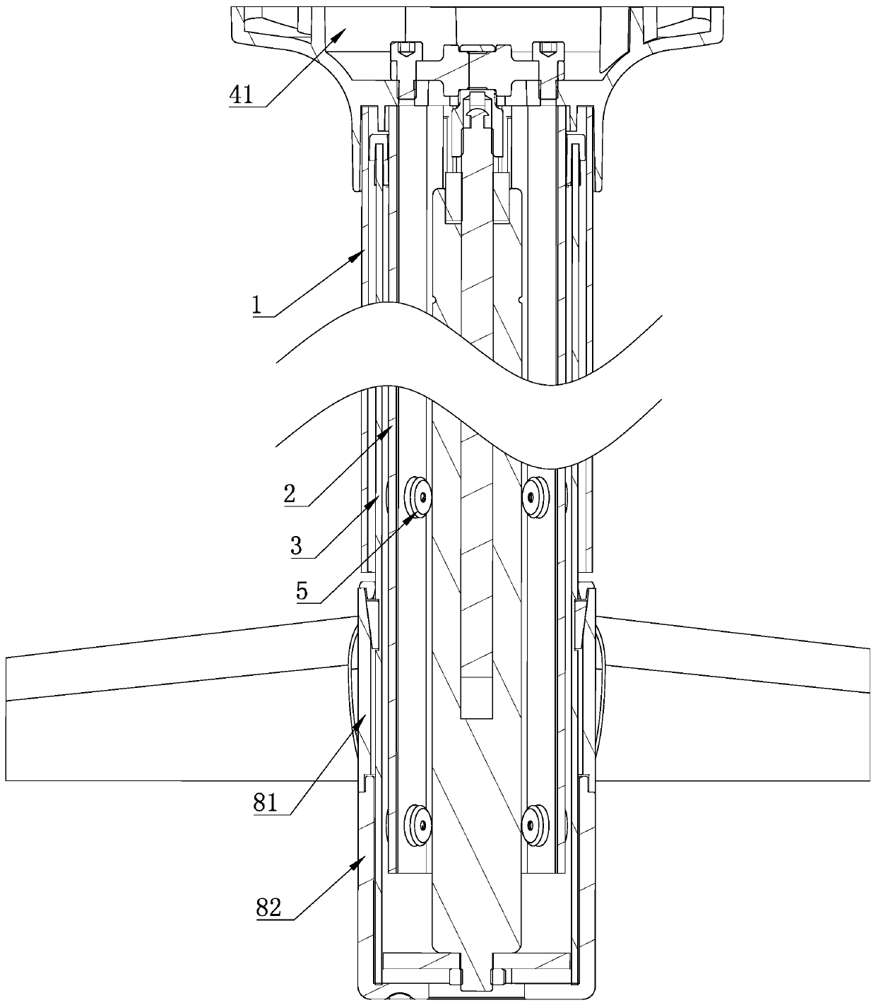
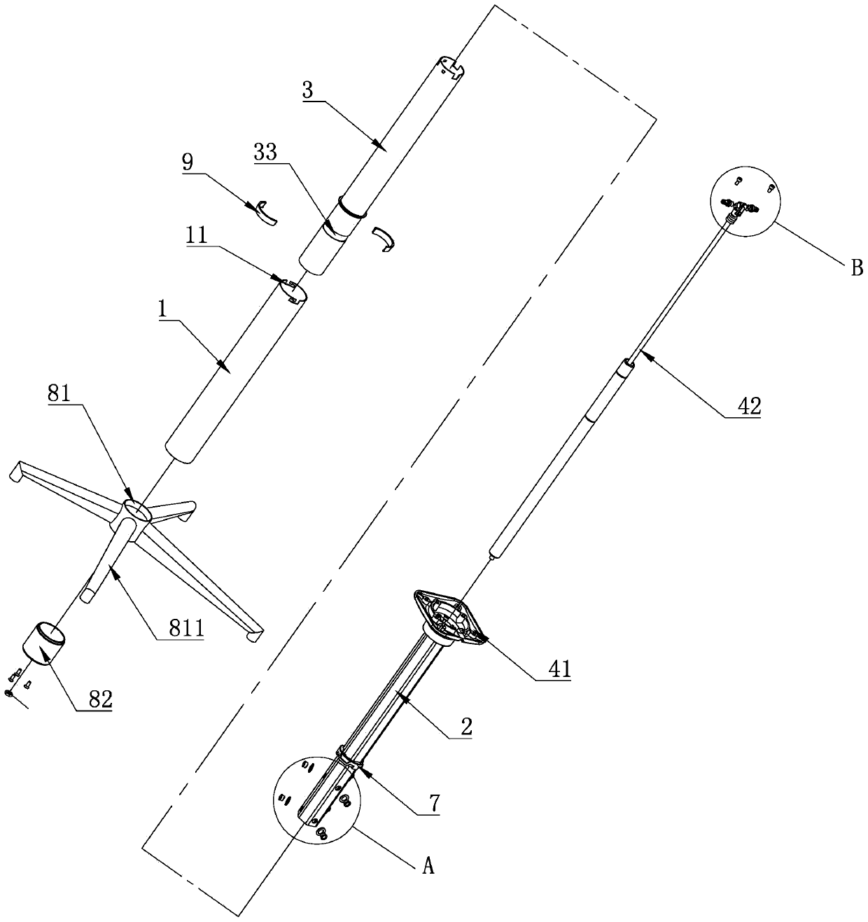
[0036] A lifting column with a rolling assembly, comprising an inner tube 2, an outer tube 3 sleeved outside the inner tube 2, a sleeve sleeve 1 sleeved outside the outer tube 3 to protect the inner tube 2 during lifting, and a sleeve sleeved on the outer tube The lifting base 8 at the bottom of 3 and the lifting assembly 4 that drives the inner tube 2 to lift up and down, the inner tube 2 and the outer tube 3 are slidably connected.

[0037]Between the inner tube 2 and the outer tube 3, there are at least two rolling assemblies 5 that prevent the inner tube 2 from shaking. In this embodiment, the inner tube 2 is preferably formed by a plurality of side walls, and the cross section of the inner tube 2 is polygonal. It is preferably hexagonal, and at least one installation hole is provided on the six side walls of the inner tube 2, and a rolling assembly 5 is respectively provided in each installation hole, and the rolling assembly 5 includes a base inserted on the inner tube 2 ...

Embodiment 2

[0042] The difference between the present embodiment and the first embodiment is that the base 51 and the adjusting gasket 6 are integrated, and the adjusting gasket 6 is in contact with the outer wall of the inner tube 2 . In this embodiment, the adjusting gasket 6 and the base 51 are arranged as an integral structure, and the base 51 of the adjusting gasket 6 with different thicknesses is selected according to the gap between the inner tube 2 and the outer tube 3, so that no matter whether the inner tube 2 or the outer tube What is the gap between 3? Each rolling assembly 5 always presses the inner wall of the outer tube 3 to prevent the rolling assembly 5 from moving between the inner tube 2 and the outer tube 3. At the same time, the rolling assembly 5 forms a support for the inner tube 2 to prevent The inner tube 2 shakes during the lifting process, and the integrated adjustment gasket 6 and base 51 make it unnecessary to assemble the adjustment gasket 6 and the base 51 du...


PUM


Abstract

The invention discloses a lifting upright post with rolling assemblies. The lifting upright post comprises an inner pipe, an outer pipe with which the inner pipe is sleeved and a lifting assembly fordriving the inner pipe to lift. The inner pipe and the outer pipe are in sliding connection, at least two rolling assemblies for preventing the inner pipe from shaking are arranged between the inner pipe and the outer pipe, the rolling assemblies are arranged on the inner pipe, and adjusting gaskets for pressing the rolling assemblies on the outer pipe are arranged between the rolling assemblies and the inner pipe. The distance between the ends, facing the inner wall of the outer pipe, of the rolling assemblies and the outer wall of the inner pipe can be adjusted by selecting the thickness ofthe adjusting gaskets, in other words, the distance between the ends, facing the inner wall of the outer pipe, of the rolling assemblies and the outer wall of the inner pipe can be adjusted accordingto the gap between the outer pipe and the inner pipe, so that the rolling assemblies always abut against the inner wall of the outer pipe, and the inner pipe is prevented from shaking in the lifting process; and rolling friction is formed between the rolling assemblies and the inner wall of the outer pipe, so that lifting of the inner pipe in the outer pipe is smoother.

Description

technical field [0001] The invention belongs to the field of lifting columns, and in particular relates to a lifting column with a rolling assembly. Background technique [0002] At present, the lifting column has been widely used. During the lifting process of the lifting column, the friction plate between the inner tube and the outer tube can prevent the inner tube from shaking. However, the friction plate increases the force on the inner tube during the lifting process. Resistance, so that the lifting of the inner tube is not smooth, and prone to jamming and other phenomena. Contents of the invention [0003] The technical problem to be solved by the present invention is to provide a lifting column with a rolling assembly that lifts smoothly and stably. [0004] In order to solve the above technical problems, the present invention adopts the following technical solutions: a lifting column with a rolling assembly, including an inner tube, an outer tube sleeved outside t...

Claims


Application Information

Patent Timeline
Patent Type & Authority Applications(China)
IPC IPC(8): F16B7/14
CPCF16B7/1409
Inventor 戎装晏龚旭良叶董通
Owner ZHEJIANG JIECHANG LINEAR MOTION TECH
Why Eureka
Try Eureka