Method for automatic color separation of ceramic tiles

A tile and automatic technology, applied in the field of tile manufacturing, can solve the problems of restricted response speed, difficulty in satisfying the response speed, and low sampling accuracy, and achieve the effect of improving system response speed, small distortion of intake information, and quick and easy replacement

Inactive Publication Date: 2011-06-15
程好学
View PDF3 Cites 19 Cited by
  • Summary
  • Abstract
  • Description
  • Claims
  • Application Information

AI Technical Summary

Problems solved by technology

[0003] Sorting is often a bottleneck process, especially for micro-powder and multi-tube fabric products, due to process fluctuations will cause a lot of color difference
At present, the sorting of color difference depends on manual work. Manual sorting is not only different due to individual color sensitivity of workers, but also has a lot to do with light and visual fatigue, so it causes great confusion in actual work. and lead to a large number of customer complaints
[0004] There are automatic detection equipments produced in foreign countries, among which the size and flatness detection are relatively mature, and the products of the Italian system company can be seen, but the color difference detection equipment has not been widely used
[0005] Domestically, Chinese patent ZL 200720051624.1 describes a machine vision-based special device for ceramic tile detection, which is used to detect the size and surface defects of ceramic tiles. The image acquisition is controlled by an incremental rotary encoder to capture the linear CCD camera, and the sampling accuracy is low. It is impossible to obtain comprehensive image color information, and it is necessary to restore and display the image of the inspected tile. When the sampling accuracy is high or the tile is large, the excessive amount of image information transmission will restrict the response speed, and real-time online inspection cannot be performed; China The tile surface quality automatic detection device described in patent ZL200520058035.7 uses a digital camera, and its disadvantage is that the images taken by the digital camera must be transmitted to the computer for processing. For large-scale tiles larger than 800MM, if you want to get a 300DPI image, you need more than 200M of information transmission The speed of its response is difficult to meet the needs of online detection. In addition, the repeatability of the image of the tile surface obtained in the moving state will be difficult to guarantee; the method and equipment for the quality inspection of ceramic tiles described in the invention patent application No. 200610123005.9, although it was inspected The tiles are paused at the shooting position to allow the camera to shoot, but there is still no good solution for the processing of large-scale tiles, especially for rectangular tiles such as 800*1200MM, which are more difficult to handle. In addition, reflection and diffraction caused by external light sources will Varies due to variations in the flatness of the brick surface, these affect the accuracy of the image and the repeatability of the shot
Therefore, there is currently no mature application of automatic color separation devices in the market

Method used


Image

  • Method for automatic color separation of ceramic tiles
  • Method for automatic color separation of ceramic tiles
  • Method for automatic color separation of ceramic tiles

Examples


Embodiment 1

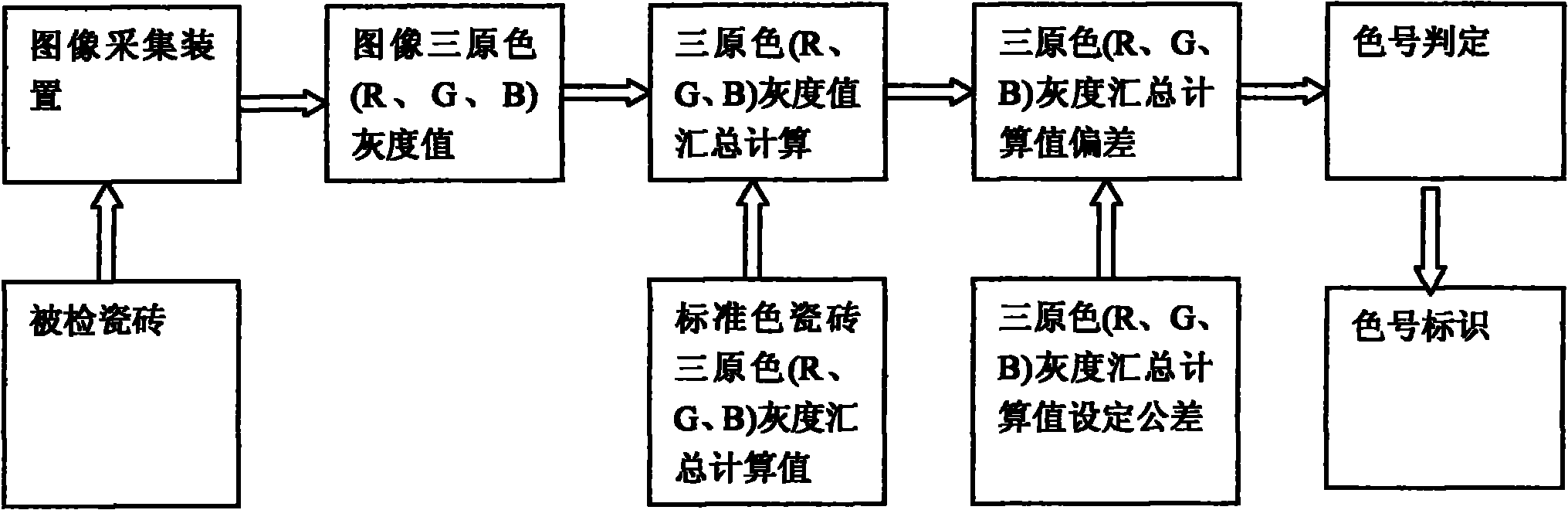
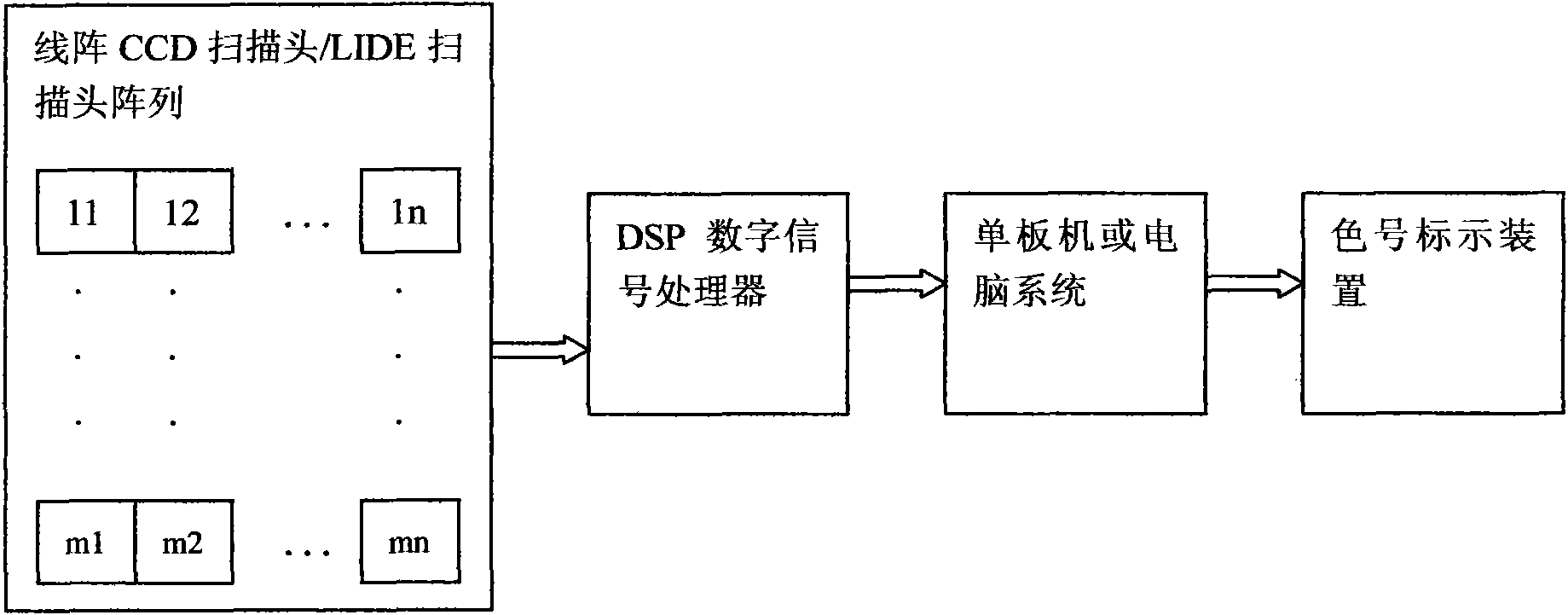
[0046] Such as figure 2As shown, the image acquisition device in this example adopts a scanner based on a linear CCD photoelectric sensor or a LIDE image sensor with N*M scanning heads forming an array of scanning heads with N columns and M rows. The number of columns N depends on the width of the detected tiles, the width of the scanning head is 200-210MM, and there is no gap between the scanning heads arranged in each row; the number of rows M depends on the speed of the pipeline, and the scanning speed multiplied by M should be greater than or equal to the speed of the pipeline. Column spacing is evenly spaced according to tile length.

[0047] Since the output of the scanning head is the analog signal of the three primary colors (R, G, B), several multi-channel DSP digital signal processing systems are used for A / D analog-to-digital conversion and summary calculation, and the calculation results are output to a computer or a single board computer for processing. Calculat...

Embodiment 2

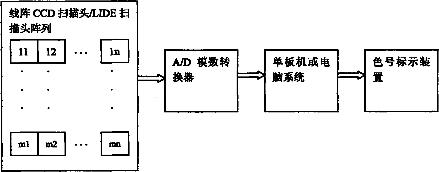
[0050] Such as image 3 As shown, the difference between this example and Example 1 is that the DSP digital signal processing system is replaced by an A / D analog-to-digital converter, and the data processing center is composed of an A / D analog-to-digital converter and a single-board computer or a computer.

Embodiment 3

[0052] Such as Figure 4 As shown, the image acquisition device in this example adopts a scanner based on a linear CCD photoelectric sensor or a LIDE image sensor with N*M scanning heads forming an array of scanning heads with N columns and M rows. The number of columns N depends on the width of the detected tiles, the width of the scanning head is 200-210MM, and there is no gap between the scanning heads arranged in each row; the number of rows M depends on the speed of the pipeline, and the scanning speed multiplied by M should be greater than or equal to the speed of the pipeline. Column spacing is evenly spaced according to tile length.

[0053] Since the scanning head outputs analog signals of the three primary colors (R, G, B), this example retains the main board of the scanner that matches the scanning head, and uses its A / D analog-to-digital conversion circuit to obtain the gray scale of the three primary colors (R, G, B) digital information. Since there are N*M outp...


PUM


Abstract

The invention discloses a method for automatic color separation of ceramic tiles, and more specifically, relates to a method for classifying ceramic tiles in different colors by quantitatively determining color values of the surface pictures of the ceramic tiles and then comparing the color values with a standard color value. The method is characterized by regarding a summarized calculation value of gray-scale values of three primary colors (RGB: Red Green Blue) of the surface pictures of the ceramic tiles as the reference for judging color numbers of the ceramic tiles. The method has the advantages of: realizing online color separation of the ceramic tiles, enhancing the accuracy of color separation, reducing labor intensity of workers and raising the automation level of separation of the ceramic tiles.

Description

Technical field: [0001] The present invention relates to a method for automatic color separation of ceramic tiles for finished product inspection in the field of ceramic tile manufacturing, and more specifically relates to a method for quantitatively measuring and summarizing grayscale values ​​of three primary colors (R, G, B) of tile surface images, through which It is a method to classify tiles of different colors by comparing the gray value summary calculation value with the corresponding value of the standard color. Background technique: [0002] At present, my country has become the world's building ceramics base, but the ceramic industry in my country is still a labor-intensive industry, especially after firing and packaging, a large amount of manpower is used. With the current rise in wages and the further demand for quality in the market, it is especially important to improve the automation level of the post-process. [0003] Sorting is often a bottleneck process, ...

Claims


Application Information

Patent Timeline
Patent Type & Authority Applications(China)
IPC IPC(8): G01J3/50G01N21/84
Inventor 程好学
Owner 程好学
Why Eureka
Try Eureka