Imaging displacement module

Active Publication Date: 2008-12-11
YOUNG OPTICS
View PDF2 Cites 12 Cited by
  • Summary
  • Abstract
  • Description
  • Claims
  • Application Information

AI Technical Summary

Benefits of technology

[0007]Accordingly, the present invention provides an imaging displacement module for switching the imaging positio

Problems solved by technology

Since the projection apparatus is mostly used for displaying large image, the user easily recognizes the net-like black areas and feels the poor display quality.
However, the prism and the projection lens of the projection apparatus are heavy and

Method used


Image

  • Imaging displacement module
  • Imaging displacement module
  • Imaging displacement module

Examples


Example

First Embodiment

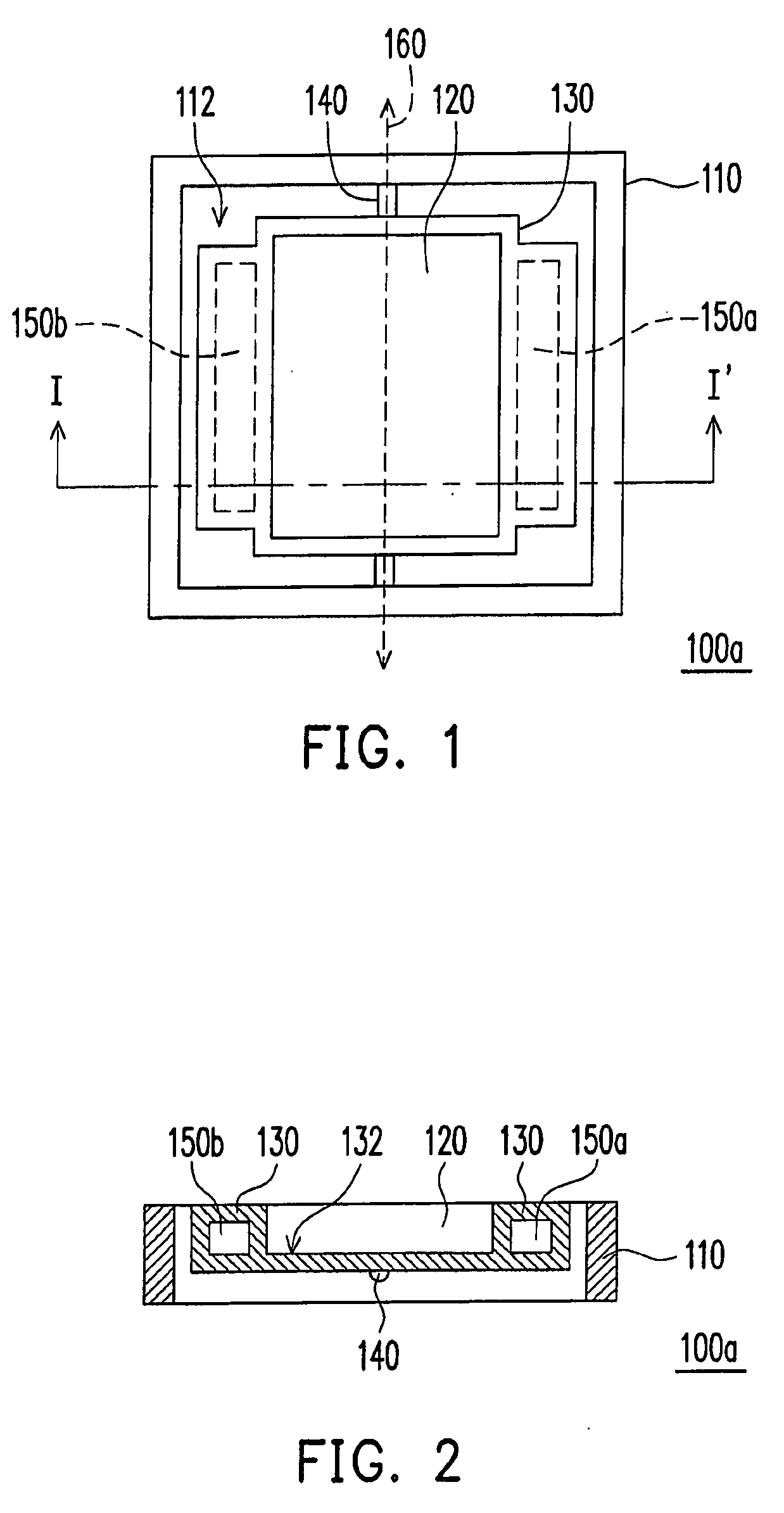
[0035]Refer to FIGS. 1 and 2, an imaging displacement module 100a includes a frame 110, an optical element 120, a carrier 130, a connecting portion 140 and at least a first actuator 150a. The frame 110 has a first opening 112, and the optical element 120, the carrier 130, the connecting portion 140 and the first actuator 150a are all disposed in the first opening 112. The carrier 130 is capable of carrying the optical element 120, and the connecting portion 140 connects between the frame 110 and the carrier 130 and capable of generating an elastic torsion around an axis 160. The first actuator 150a is disposed at a side of the carrier 130 and capable of driving the carrier 130 to vibrate periodically around the connecting portion 140.

[0036]In the present embodiment, a plane formed by the axis 160 of the connecting portion 140 and a mass center of the optical element 120 is perpendicular to a surface of the optical element 120. Furthermore, the optical element is a re...

Example

Second Embodiment

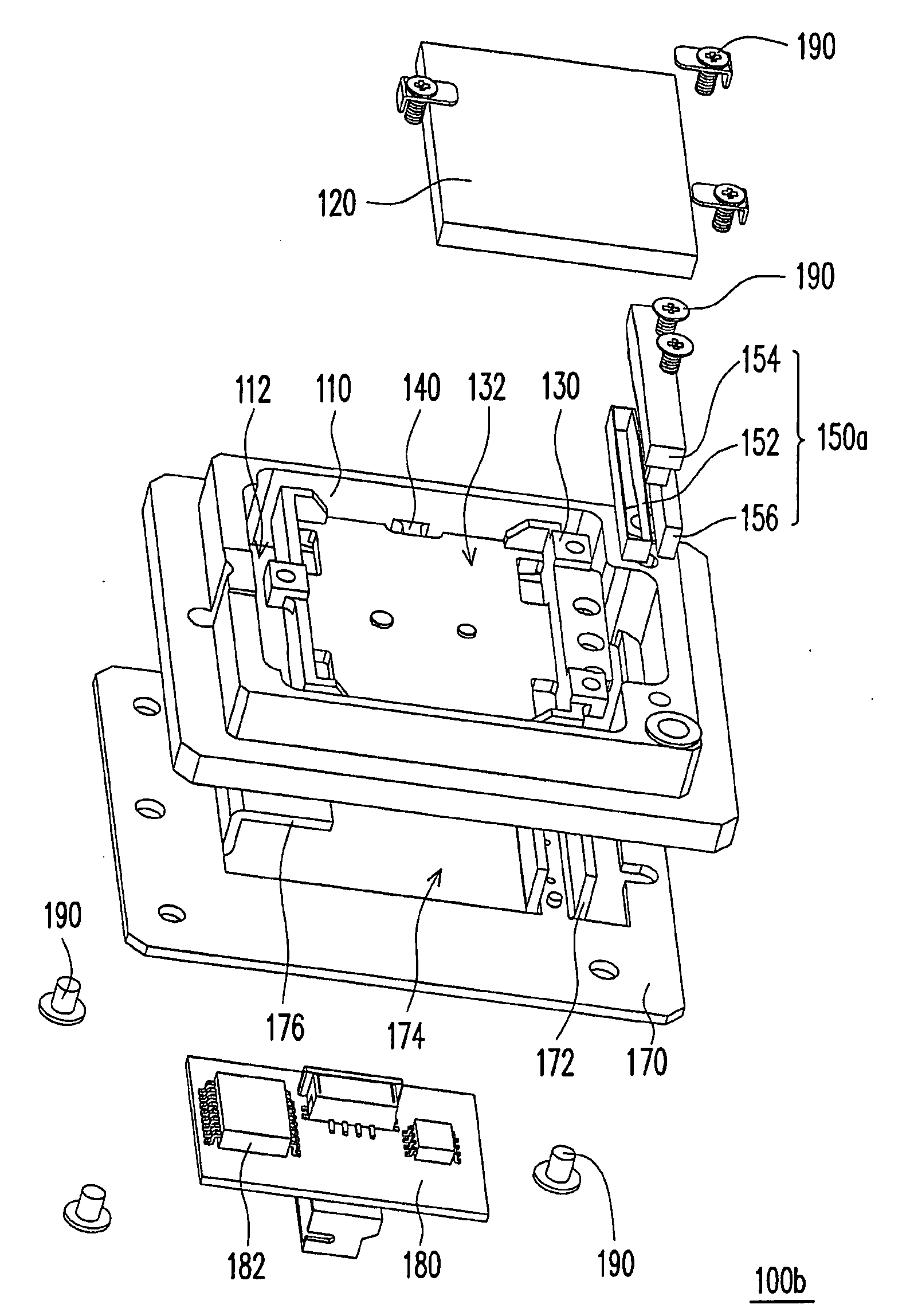
[0042]Refer to FIGS. 4 to 6, in the present embodiment, an imaging displacement module 100b has a structure that an connecting portion 140 thereof includes two connecting rods respectively disposed at two sides of a carrier 130. Axial lines of the connecting rods are coinciding with each other to form an axis 160 as a pivot. In addition, the imaging displacement module 100b does not include a second actuator 150b.

[0043]In the present embodiment, the imaging displacement module 100b may further includes a base 170. The frame 110 is disposed, for example, on the base 170, and the first actuator 150a is disposed, for example, between the carrier 130 and the base 170. Furthermore, the first actuator 150a is, for example, a VCM, and the first actuator 150a includes a coil 152, a coil frame 154 and a magnet 156, and the base 170 has an accommodating portion 172. The coil 152 is, for example, wrapped around the coil frame 154 and connected to a side of the carrier 130 thr...

Example

Third Embodiment

[0048]Refer to FIGS. 7 and 8, in the present embodiment, an imaging displacement module 100c has a structure that a connecting portion 140 includes two connecting rods respectively disposed at two sides of a carrier 130. Axial lines of the connecting rods are coinciding with each other to form an axis 160. Moreover, the connecting rods are U-shaped rods or ∩-shaped rods, for example. Furthermore, an optical element 120 is a transparent glass plate or a transparent plastic plate instead of a reflective mirror, and the carrier 130 has a third opening 134 instead of a groove 132. In addition, the optical element 120 is installed in the third opening 134, for example, so that the image light beam passes through the optical element 120.

[0049]In the present embodiment, the frame 110, the carrier 130 and the connecting portion 140 are not formed integrally. The connecting portion 140 is connected to the frame 110 and the carrier 130 through locking elements 190. It should b...


PUM


Abstract

An imaging displacement module including a frame, an optical element, a carrier, a connecting portion and at least a first actuator is provided. The frame has a first opening, and the optical element, the carrier, the connecting portion and the first actuator are all disposed in the first opening. The carrier is capable of carrying the optical element, and the connecting portion connects between the frame and the carrier and capable of generating an elastic torsion around an axis. The first actuator is disposed at a side of the carrier and capable of driving the carrier to vibrate periodically.

Description

CROSS-REFERENCE TO RELATED APPLICATION[0001]This application claims the priority benefit of Taiwan application serial no. 96209227, filed on Jun. 5, 2007. All disclosure of the Taiwan application is incorporated herein by reference.BACKGROUND OF THE INVENTION[0002]1. Field of the Invention[0003]The present invention generally relates to an imaging displacement module. More particularly, the present invention relates to an imaging displacement module capable of increasing the resolution of image.[0004]2. Description of Related Art[0005]In recent years, many kinds of display apparatus such as liquid crystal display (LCD) panel, plasma display panel (PDP) and projection apparatus are broadly used in daily life. In particular, projection apparatus is more suitable to display large images. Therefore, projection apparatus has gradually become an indispensable technique for displaying large images. In general, when the projection apparatus projects an image on a screen, black areas exist b...

Claims


Application Information

Patent Timeline
IPC IPC(8): G03B21/28G03B21/14
CPCG02B26/105G02B27/46G03B21/14G03B21/28
Inventor CHEN, YI-CHANGLIN, CHIH-CHIEN
Owner YOUNG OPTICS
Why Eureka
Try Eureka