
Roofing cart

a roofer and trolley technology, applied in the field of trolleys, can solve the problems of inefficient and uncomfortable working positions, and achieve the effect of safe and convenient operating positions for the roofer

Inactive Publication Date: 2008-12-18
TWARDZIK JEFFERY W +1
View PDF20 Cites 6 Cited by
  • Summary
  • Abstract
  • Description
  • Claims
  • Application Information

AI Technical Summary

Benefits of technology

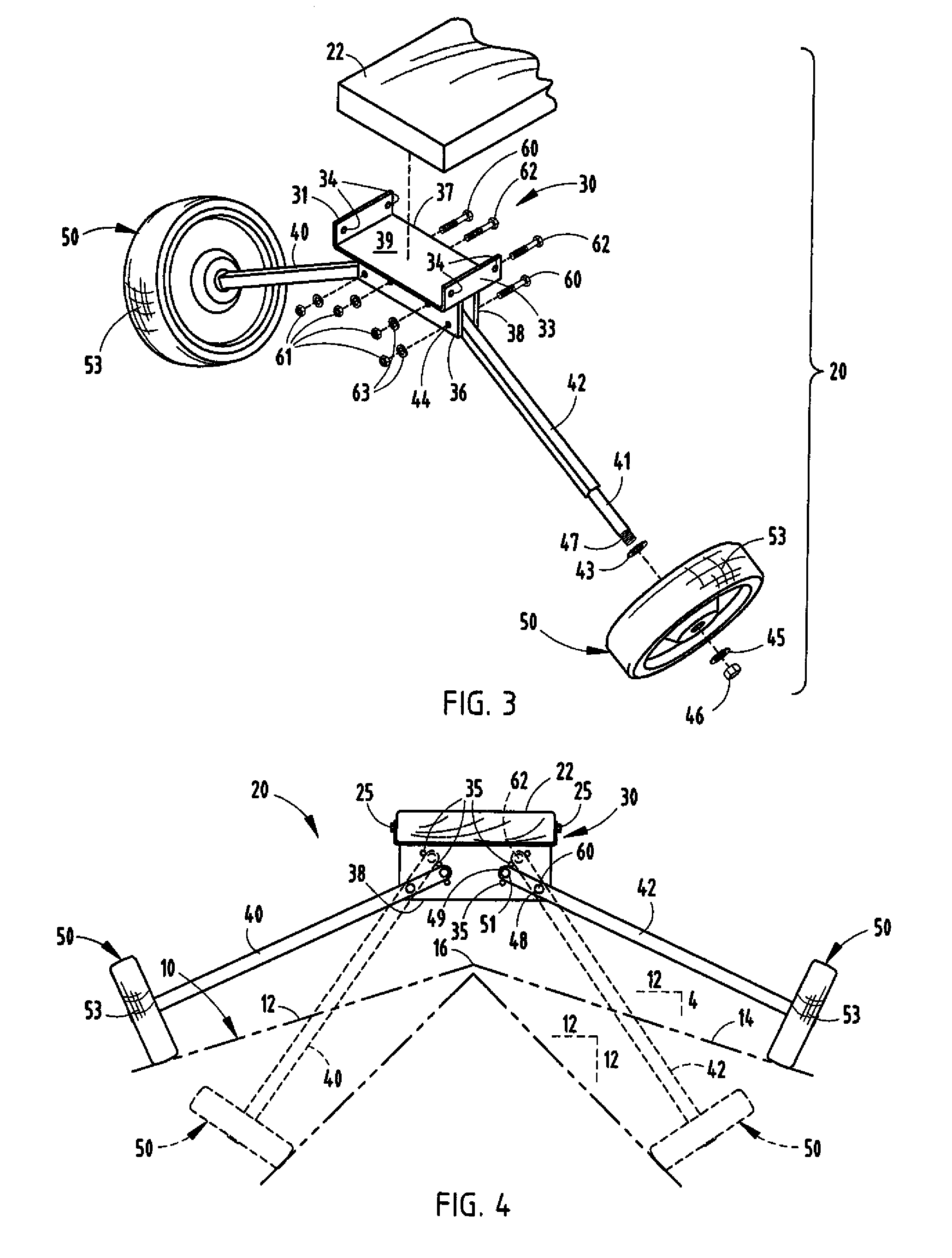
[0004]The ridge roofing cart of the present invention satisfies this need by providing an elongated platform on which a roofer can sit and which includes four wheels mounted to pairs of axles to position wheels on opposite sides of the roof ridge. The angles of the axles can be adjusted, such that opposed wheels remain in a plane generally orthogonal to the slanted roof sides while the platform is longitudinally centered along the ridge and can easily be rolled along the roof. The platform has space for holding shingles as well as providing a seating area for the roofer. The axles are mounted to the center platform by a bracket which allows the angle of the axles to be adjusted to correspond to different pitched roofs so that the cart can easily travel along the ridge of a roof and maintain a safe and convenient operating position for the roofer.
[0005]The present invention comprises mounting brackets for receiving an elongated support platform. Each bracket includes spaced plates for receiving an axle between the plates on each side thereof and an aperture for receiving an axle pivot pin at one position on the bracket. Each bracket has a plurality of apertures spaced from the pivot aperture for setting the angular position of the axle on each side of the bracket in relationship to the support platform corresponding to standard roof pitch angles. The brackets can be mounted at opposite ends of a support platform to define a cart in which the axles rotatably hold wheels which span the ridge of a roof. Such an arrangement allows the support platform to be centered over the roof ridge and maintains the cart in alignment with the roof ridge as the roofer applies roof ridge shingles and moves along the roof of a building utilizing the cart. Such a cart, therefore, greatly improves the efficiency of applying roof ridge shingles as well as a safe and effective manner for the workmen to install shingles along the roof ridge.

Problems solved by technology

Such working positions are, at best, inefficient and uncomfortable.

Method used


Image

  • Roofing cart
  • Roofing cart
  • Roofing cart

Examples


Embodiment Construction

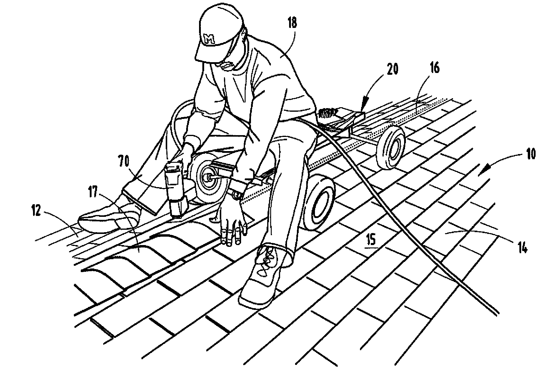
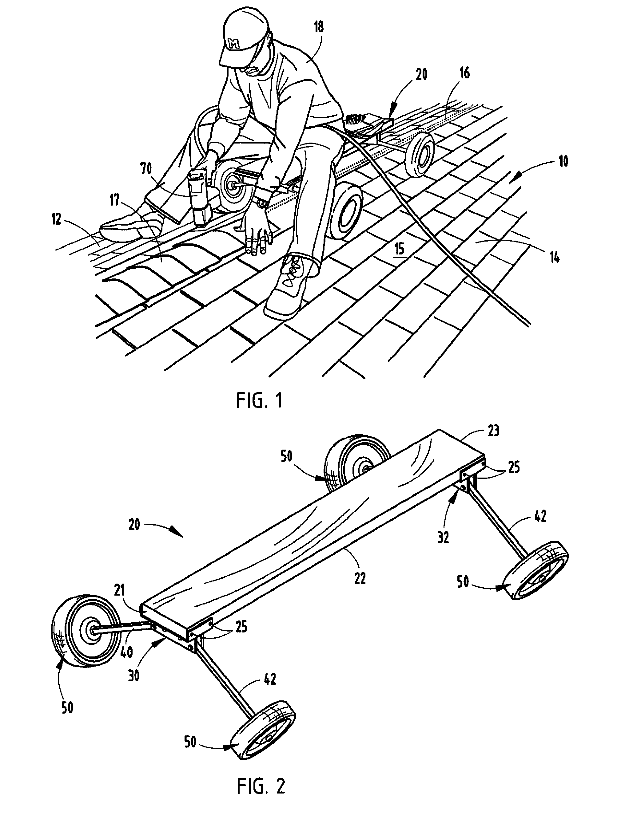
[0011]FIG. 1 shows a typical building 10 which has a pair of slanted roof sections 12 and 14 which converge along a peak or ridge 16. Roof sections 12 and 14 are shingled in a conventional manner with overlapping shingles 15 typically placed on the roof starting at the lower edge or eaves and overlapping until they abut adjacent the ridge 16 from sides 12 and 14. The ridge 16 is subsequently shingled with overlapping shingles 17 by the roofer 18 utilizing, in the preferred embodiment of this invention, the ridge roofing cart 20 of the present invention.

[0012]Cart 20, as best seen in FIG. 2, has an elongated center platform 22 which can be a precut dimensioned lumber, such as a 2×8 piece of lumber, which is anywhere from three to four feet in length, although it can be any desired length or formed of a molded polymeric material, fiberglass, or other weatherproof material of sufficient strength. Typically, cart 20 will employ a wooden central platform made of pressure-treated wood.

[00...


PUM


Abstract

A ridge roofing cart can be made using mounting brackets for receiving an elongated support platform. Each bracket includes spaced plates for receiving an axle between the plates on each side thereof and an aperture for receiving an axle pivot pin at one position on the bracket. Each bracket has a plurality of apertures spaced from the pivot aperture for setting the angular position of the axle on each side of the bracket in relationship to the support platform corresponding to standard roof pitch angles. The brackets can be mounted at opposite ends of a support platform to define a cart in which the axles rotatable hold wheels which span the ridge of a roof.

Description

BACKGROUND OF THE INVENTION[0001]The present invention relates to a cart having adjustable angled axles for spanning the apex of roofs of different pitches to facilitate the installation of roof ridge shingles or coverings.[0002]When the shingles or other protective covering for a roof have been applied from the lower edge of the roof to the peak or ridge, the ridge itself is then shingled or otherwise covered to seal the roof from environmental conditions. While a variety of carriers have been developed for holding shingles in position on a side of a roof to be available for use by the roofer, they all extend on one side of the roof. Typically, the roof ridge, however, is shingled by a worker bending or kneeling to one side of the ridge and utilizing a nailing gun to place individual shingles in overlapped, sealed relationship. Sometimes the roofer will sit and straddle the ridge during such installation. Such working positions are, at best, inefficient and uncomfortable.[0003]Thus...

Claims


Application Information

Patent Timeline
IPC IPC(8): B62M1/18
CPCA47C9/027E04D15/02
Inventor TWARDZIK, JEFFERY W.BONENFANT, MARK L.
Owner TWARDZIK JEFFERY W
Learn More