Method, apparatus and program for image processing

a technology of image processing and program, applied in the field of image processing, can solve the problems of slow shutter speed, difficult to hold the camera firmly, out of focus camera, etc., and achieve the effects of improving the accuracy of blur discrimination

Active Publication Date: 2008-12-18
FUJIFILM CORP +1
View PDF8 Cites 69 Cited by
  • Summary
  • Abstract
  • Description
  • Claims
  • Application Information

AI Technical Summary

Benefits of technology

[0167]According to the second image processing method and apparatus, in discriminating the blurred state of a digital photograph image, the imaging condition information at the time of imaging is obtained, and edge detecting conditions for discriminating the blur, conditions for discriminating whether the image in question is a normal image or a blurred image, and conditions for discriminating the camera shake blur are adjusted based on the imaging conditions using the fact that the imaging conditions will reflect the shakiness and camera shake inducing direction of the digital photograph image, so that the accuracy of the discrimination may be improved.
[0168]Further, the discrimination accuracy of the blur may be improved also for the image with a shallow depth of field by limiting the central region of a digital photograph image, which is more likely to be the main subject region, as the region for detecting the edges for the image with a shallow depth of field based on the depth of field reflected by the imaging condition information.
[0169]The blur discrimination accuracy may be improved for the images obtained by the auxiliary digital cameras of mobile phones, by obtaining the model information of the mobile phone, obtaining the shakiness and camera shake inducing direction of the image based on the model information, and adjusting the edge detecting conditions such that the greater the shakiness, the greater the number of directions for detecting edges, or closer the region is to the camera shake inducing direction, the greater the number of directions for detecting edges.
[0170]According to the third image processing method and apparatus, the image correction for the digital photograph image is implemented by extracting the main subject region from the digital photograph image, and setting the parameter for correcting the blur using the image of the main subject region, so that no user involvement is required for determining the region for setting the parameter. In particular, for the image with a shallow depth of field, the accuracy of the image correction may be improved by setting the correction parameter using only the image of the main subject region to which the image correction is required the most. Further, the correction parameter is obtained using the image of the main subject region, so that no additional device is required for obtaining the information related to the camera shake at the time of imaging, thereby the size of the imaging device may be kept small, which is especially advantageous for the auxiliary digital cameras of mobile phones for which the miniaturization is the mandatory requirement.
[0171]According to the fourth image processing method and apparatus of the present invention, the image correction for the digital photograph image is implemented by discriminating if it is an image with a shallow depth of field, and setting the correction parameter using the image of the main subject region for the digital photograph image with a shallow depth of field, so that the similar effect as that of the third image processing method and apparatus may be obtained. In addition, the image correction for the images other than those with shallow depth of fields is implemented by setting the correction parameter using the entire digital photograph image, so that the accuracy of the image correction may be improved for the images other than those with shallow depth of fields.
[0172]According to the fifth image processing method and apparatus of the present invention, the image correction for the digital photograph image is implemented by calculating the certainty factor that indicates likelihood that the digital photograph image is an image with a shallow depth of field, and using the parameter obtained through a weighting addition of the parameter which has been set using the image of the main subject region (a first parameter) and the parameter which has been set using the entire digital photograph image or the image of the region other than the main subject region (a second parameter) such that the greater the certainty factor, the heavier the weighting of the first parameter, so that the similar effect as that of the fourth image processing method and apparatus may be obtained. In addition, a good correction effect may be obtained even when there is a slight difference in the discrimination of the depth of field of the digital photograph image.

Problems solved by technology

Such a blurred image may result from the camera being out of focus at the time of imaging, which is known as the defocus blur.
On the other hand, mobile cameras have a problem that it is difficult to hold them firmly at the time of imaging, since the body (mobile phone) is not designed for exclusive use for imaging.
In addition, the mobile cameras have no photoflash, resulting in a slower shutter speeds than those of ordinary digital cameras.
Attaching a device for obtaining the direction and width of the camera shake to the auxiliary camera of a mobile phone is unrealistic since the miniaturization of the mobile phone is one of the focal points of competition among the manufactures along with its capability and cost.
Therefore, the method described in Japanese Unexamined Patent Publication No. 2002-112099 may not be applied for mobile cameras.
Also, the method described in Japanese Unexamined Patent Publication No. 7 (1995)-121703 has a problem that it requires longer processing time, and hence inefficient, since the steps of deterioration function setting, image restoration, image evaluation, and resetting of the deterioration function need to be repeated.

Method used


Image

  • Method, apparatus and program for image processing
  • Method, apparatus and program for image processing
  • Method, apparatus and program for image processing

Examples


first embodiment

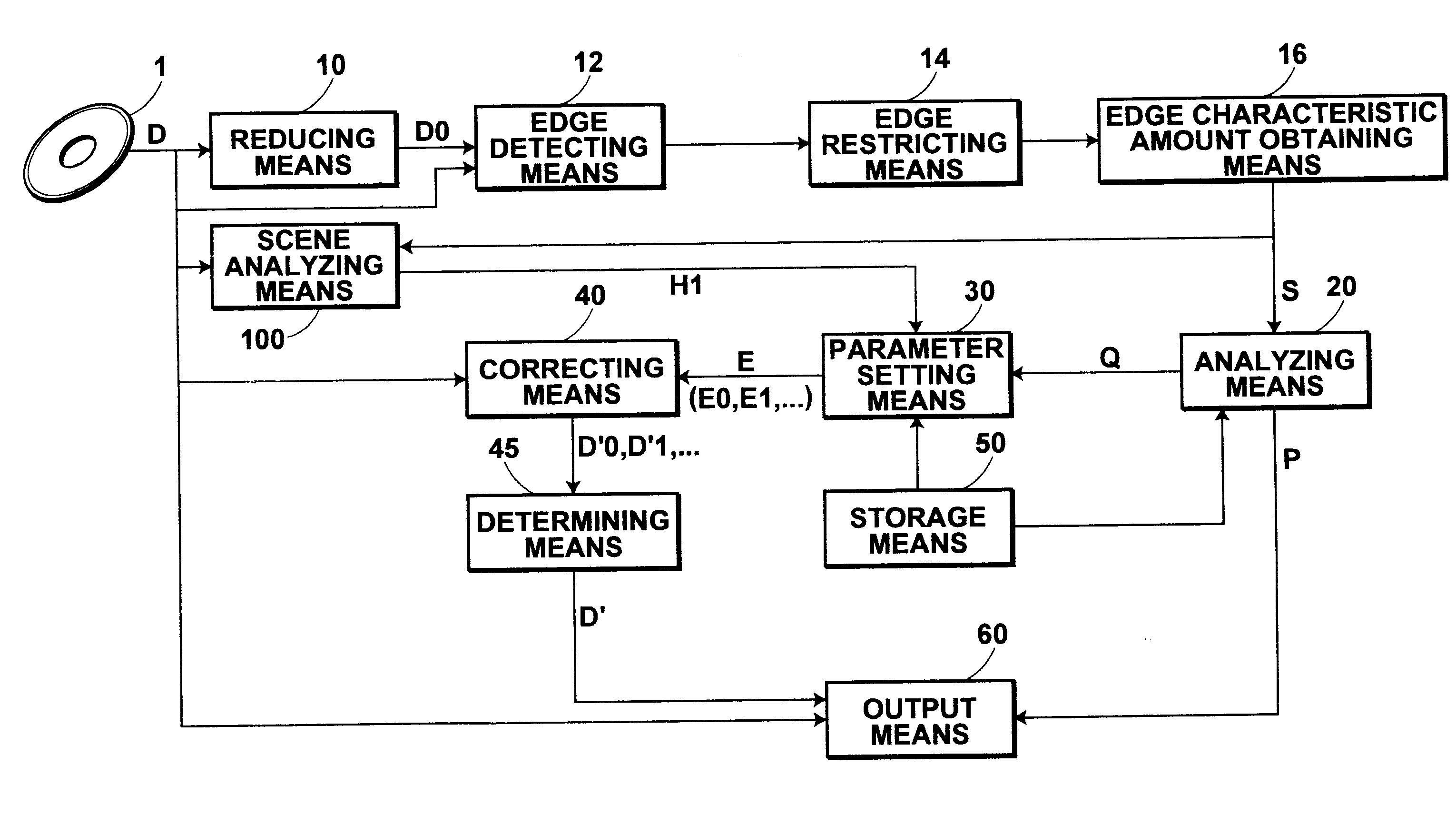
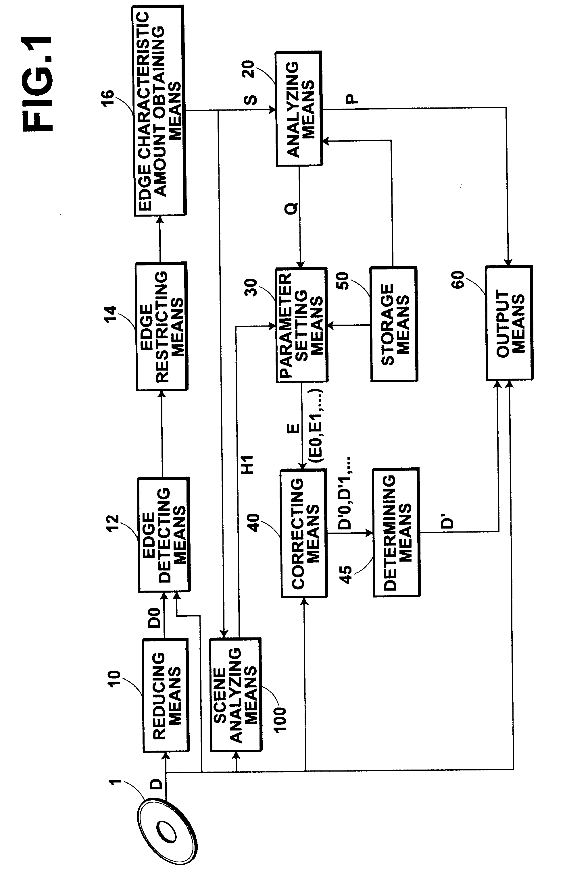
[0261]FIG. 1 is a block diagram of an image processing system according to the present invention. The image processing system shown in FIG. 1 is a system for implementing the image processing by reading out photograph images (images) from a recording medium 1 that contains images obtained by auxiliary digital cameras of mobile phones (mobile cameras). The recording medium 1 contains groups of images, each comprising a number of images. Here, the description will be made taking a single image D as an example.

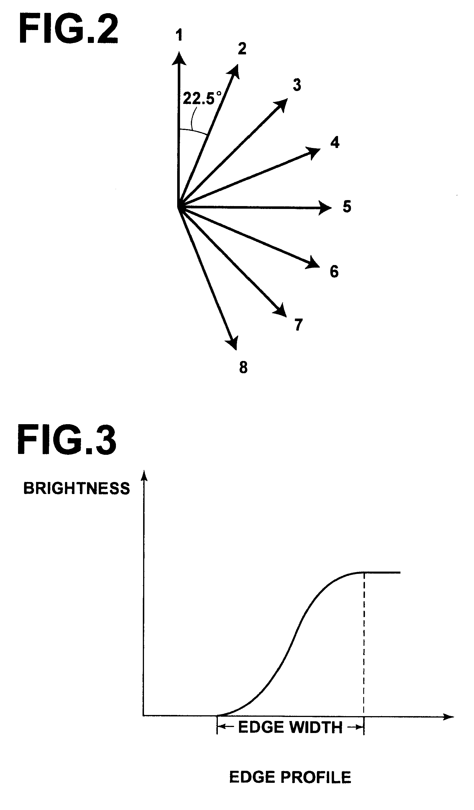
[0262]As shown in the drawing, the image processing system according to the present embodiment comprises: a reducing means 10 for reducing the image D read out from the recording medium 1 to obtain a reduced image D0 of the image D; an edge detecting means 12 for detecting edges in each direction of 8 directions shown in FIG. 2 using the image D and reduced image D0; an edge restricting means 14 for eliminating invalid edges from among those detected by the edge detecting means 1...

second embodiment

[0347]FIG. 19 is a block diagram illustrating the configuration of an image processing system according to the present invention. The configuration of the image processing system according to the present embodiment is similar to that of the image processing system according to the embodiment shown in FIG. 1, and components identical to those used in the embodiment shown in FIG. 1 are given the same numerals. The image processing system of the present invention differs from that of the embodiment shown in FIG. 1 only in the determining means which is given a reference numeral of 45′ instead of 45. Hence, the description will be made only for the determining means 45′.

[0348]The determining means 45′ of the image processing system according to the embodiment shown in FIG. 19 comprises an evaluating means (not shown) for evaluating the correction effect for each of the corrected images obtained by the correcting means 40. It determines one of the corrected images having the best correct...

third embodiment

[0371]FIG. 21 is a block diagram illustrating the configuration of an image processing system A according to the present invention. The image processing system A shown in FIG. 21 is adapted to implement image processing by reading out the photograph images (images) from a recording medium 1 storing images obtained by digital cameras. The recording medium 1 contains groups of images, each comprising a number of images. Here, the description will be made taking up a single image D as an example.

[0372]As shown in FIG. 21, the image processing system A of the present embodiment comprises: a condition setting means 300a for setting edge detecting conditions and discriminating conditions, and transmitting them respectively to an edge detecting means 212a and analyzing means, to be described later; a reducing means 210a for reducing the image D read out from the recording medium 1 to obtain a reduced image D0 of the image D; an edge detecting means 212a for detecting edges in each directio...


PUM


Abstract

An analyzing means first calculates the blur direction and blur level of a digital photograph image based on edge widths and histograms of the edge widths obtained in each direction, and discriminates whether the image is a blurred image or a normal image. Then, it further calculates the camera shake level and blur width for the image discriminated to be a blurred image. A parameter setting means sets a one-dimensional correction mask and a two-dimensional correction mask based on the blur width. It also sets a correction level based on the blur level. It further makes an adjustment to the ratio between the one-dimensional and two-dimensional correction masks based on the camera shake level.

Description

BACKGROUND OF THE INVENTION[0001]1. Field of the Invention[0002]The present invention relates to an image processing method and apparatus for obtaining information related to an image blur from a digital photograph image, in particular, from that obtained by the auxiliary digital camera of a mobile phone. The present invention also relates to a program that causes a computer to execute the method.[0003]2. Description of the Related Art[0004]Various image processing techniques are performed on digital photograph images obtained by reading devices, such as scanners, through photoelectrical reading from the photograph images recorded on camera films, such as negative films or color reversal films, or those obtained by digital still cameras (DSCs) before printing. Such image processing techniques include a blurred image restoration technique for removing blurs from blurred images.[0005]Some of the photograph images obtained through imaging subjects may be blurred. Such a blurred image m...

Claims


Application Information

Patent Timeline
Patent Type & Authority Applications(United States)
IPC IPC(8): H04N5/228G06K9/40
CPCG06K9/00228G06K9/4647H04N5/23254H04N5/23267H04N2007/145G06V40/161G06V10/507H04N23/6811H04N23/683
Inventor AOYAMA, TATSUYA
Owner FUJIFILM CORP
Why Eureka
Try Eureka