Zoom lens system and image pickup apparatus including the same

a technology of zoom lens and image pickup, which is applied in the field of zoom lens system, can solve the problems of difficult to compensate for such aberrations in a good manner, the simple increase of the refractive power of the lens group, and the long total length of the zoom lens system. , to achieve the effect of high optical performance, simple lens configuration, and high zoom ratio

Inactive Publication Date: 2008-12-18
CANON KK
View PDF4 Cites 9 Cited by
  • Summary
  • Abstract
  • Description
  • Claims
  • Application Information

AI Technical Summary

Benefits of technology

[0012]The present invention provides a zoom lens system that has a high zoom ratio and a simple, compact lens configuration while exhibiting high optical performance at all zoom positions.

Problems solved by technology

Moreover, a zoom lens system that includes lens groups that move large distances during zooming and focusing has a long total length.
However, a simple increase of the refractive power of the lens group increases changes in aberrations during zooming.
It is difficult to compensate for such aberrations in a good manner.

Method used


Image

  • Zoom lens system and image pickup apparatus including the same
  • Zoom lens system and image pickup apparatus including the same
  • Zoom lens system and image pickup apparatus including the same

Examples


numerical example 1

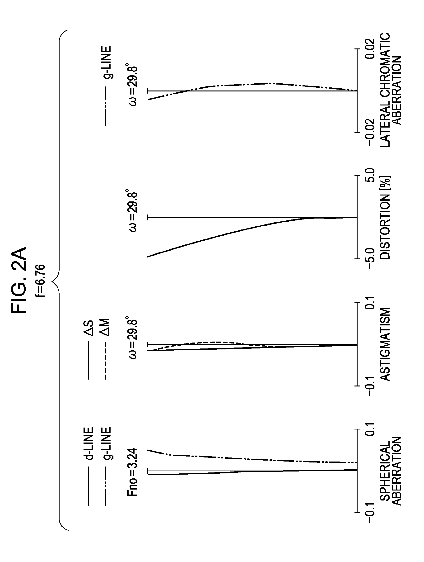
[0111]f=6.76˜32.19 Fno=3.24˜5.88 2ω=59.6˜13.6

[0112]R 1=36.425 D 1=0.90 N 1=1.846660 ν 1=23.9

[0113]R 2=20.870 D 2=2.60 N 2=1.804000 ν 2=46.6

[0114]R 3=423.219 D 3=variable

[0115]* R 4=−120.928 D 4=1.65 N 3=1.848620 ν 3=40.0

[0116]* R 5=5.369 D 5=1.97

[0117]R 6=9.531 D 6=1.70 N 4=1.922860 ν 4=18.9

[0118]R 7=21.305 D 7=variable

[0119]* R 8=5.124 D 8=2.30 N 5=1.882997 ν 5=40.8

[0120]R 9=16.216 D 9=0.70 N 6=1.808095 ν 6=22.8

[0121]R10=4.203 D10=0.52

[0122]R11=10.171 D11=1.80 N 7=1.487490 ν 7=70.2

[0123]R12=−14.353 D12=variable

[0124]R13=12.341 D13=1.80 N 8=1.487490 ν 8=70.2

[0125]R14=131.500 D14=variable

[0126]R15=∞D15=1.00 N 9=1.516330 ν 9=64.1

[0127]R16=∞

[0128]\Focal Length 6.76 14.94 32.19

[0129]variable Range\

[0130]D 3 1.20 6.79 16.40

[0131]D 7 15.09 4.97 1.17

[0132]D12 5.85 11.02 21.19

[0133]D14 4.69 6.23 3.85

[0134]Aspherical Coefficient

[0135]4th surface: k=0.00000e+00 A=0 B=1.11274e−05

[0136]C=0.00000e+00 D=0.00000e+00 E=0.00000e+00

[0137]5th surface: k=−2.79279e+00 A=0 B=1.72320e−03

[0138]C=−3.57723e−...

numerical example 2

[0141]f=6.76˜32.35 Fno=3.30˜5.69 2ω=59.6˜13.6

[0142]R 1=33.137 D 1=0.90 N 1=1.846660 ν 1=23.9

[0143]R 2=19.192 D 2=2.80 N 2=1.804000 ν 2=46.6

[0144]R 3=242.172 D 3=variable

[0145]* R 4=−96.261 D 4=1.65 N 3=1.848620 ν 3=40.0

[0146]* R 5=5.396 D 5=1.89

[0147]R 6=9.316 D 6=1.80 N 4=1.922860 ν 4=18.9

[0148]R 7=20.239 D 7=variable

[0149]* R 8=5.232 D 8=2.10 N 5=1.882997 ν 5=40.8

[0150]R 9=8.992 D 9=0.90 N 6=1.922860 ν 6=18.9

[0151]R10=4.476 D10=0.49

[0152]R11=10.995 D11=1.70 N 7=1.603112 ν 7=60.6

[0153]R12=−17.967 D12=variable

[0154]R13=11.887 D13=1.80 N 8=1.487490 ν 8=70.2

[0155]R14=91.923 D14=variable

[0156]R15=∞D15=1.00 N 9=1.516330 ν 9=64.1

[0157]R16=∞

[0158]\Focal Length 6.76 15.26 32.35

[0159]variable Range\

[0160]D 3 1.20 7.43 16.37

[0161]D 7 16.47 5.78 1.68

[0162]D12 7.50 12.19 20.99

[0163]D14 3.91 5.67 3.96

[0164]Aspherical Coefficient

[0165]4th surface: k=0.00000e+00 A=0 B=1.61717e−05

[0166]C=0.00000e+00 D=0.00000e+00 E=0.00000e+00

[0167]5th surface: k=−2.66336e+00 A=0 B=1.62355e−03

[0168]C=−3.08981e−05 ...

numerical example 3

[0171]f=6.76˜32.35 Fno=2.93˜5.35 2ω=59.6˜13.6

[0172]R 1=37.196 D 1=0.90 N 1=1.846660ν 1=23.9

[0173]R 2=21.532 D 2=2.70 N 2=1.804000 ν 2=46.6

[0174]R 3=440.672 D 3=variable

[0175]* R 4=−107.214 D 4=1.65 N 3=1.848620 ν 3=40.0

[0176]* R 5=5.516 D 5=1.93

[0177]R 6=9.693 D 6=1.80 N 4=1.922860 ν 4=18.9

[0178]R 7=21.867 D 7=variable

[0179]* R 8=5.118 D 8=2.30 N 5=1.882997 ν 5=40.8

[0180]R 9=16.888 D 9=0.70 N 6=1.808095 ν 6=22.8

[0181]R10=4.211 D10=0.52

[0182]R11=10.186 D11=1.80 N 7=1.487490 ν 7=70.2

[0183]R12=−14.473 D12=variable

[0184]R13=14.277 D13=1.80 N 8=1.603112 ν 8=60.6

[0185]R14=91.600 D14=variable

[0186]R15=∞D15=0.50 N 9=1.516330 ν 9=64.1

[0187]R16=∞

[0188]\Focal Length 6.76 14.94 32.35

[0189]Variable Range\

[0190]D 3 1.20 7.61 17.46

[0191]D 7 14.85 4.83 1.01

[0192]D12 5.25 9.95 20.08

[0193]D14 4.84 6.36 3.70

[0194]Aspherical Coefficient

[0195]4th surface: k=0.00000e+00 A=0 B=6.10931e−06

[0196]C=0.00000e+00 D=0.00000e+00 E=0.00000e+00

[0197]5th surface: k=−2.94241e+00 A=0 B=1.67564e−03

[0198]C=−3.45129e−05 ...


PUM


Abstract

A simple, compact, high-zoom-ratio zoom lens system exhibiting high optical performance at all zoom positions is provided. The system includes, in order from the object side to the image side, first to fourth lens groups having positive, negative, positive, and positive refractive powers, respectively. The first-to-second-lens-group distance becomes the smallest during zooming. The first lens group resides closer to the object at a telephoto end than at a wide-angle end. The lens groups move such that the second-to-third-lens-group distance is smaller and the third-to-fourth-lens-group distance is larger at the telephoto end than at the wide-angle end. The second lens group includes, in order from the object side to the image side, negative and positive lens elements. First-to-second-lens-group distances d1w and d1t at the wide-angle end and at the telephoto end, respectively, and the smallest first-to-second-lens-group distance d1min obtained during zooming are appropriately set.

Description

BACKGROUND OF THE INVENTION[0001]1. Field of the Invention[0002]The present invention relates to zoom lens systems suitable for cameras such as video cameras, silver-halide-film cameras, broadcast cameras, and digital still cameras, and to image pickup apparatuses including the same.[0003]2. Description of the Related Art[0004]Recent image pickup apparatuses, such as video cameras, digital still cameras, broadcast cameras, and silver-halide-film still cameras, that include solid-state image pickup devices have higher functions and are of smaller sizes.[0005]Image taking optical systems included in such image pickup apparatuses are desired to be compact lens systems with a short total length and a high zoom ratio and to exhibit good optical performance at all zoom positions.[0006]For example, Japanese Patent Laid-Open No. 3-296706 and U.S. Pat. Nos. 6,975,461 and 6,853,496 disclose compact four-group zoom lens systems that have a high zoom ratio and perform zooming by moving individu...

Claims


Application Information

Patent Timeline
Patent Type & Authority Applications(United States)
IPC IPC(8): G02B15/16G03B19/02G03B19/18
CPCG02B15/173G02B15/144113
Inventor ITOH, YOSHINORI
Owner CANON KK
Why Eureka
Try Eureka