

Display device having pair of glass substrates and method for cutting it
a display device and glass substrate technology, applied in the field of display devices, can solve the problems of difficult use of external cutting scribing methods, easy waste residues of internal cutting scribing methods, and easy cracking and/or chipping at the start of scribing, so as to improve yield rate, prevent defects in outer dimensions, and improve the outer dimension of the resulting display device.
Inactive Publication Date: 2008-12-18
JAPAN DISPLAY WEST
View PDF1 Cites 26 Cited by
- Summary
- Abstract
- Description
- Claims
- Application Information
AI Technical Summary
Benefits of technology
[0025]The cutting method according to an aspect of the invention can be applied even when the thickness of each of the bonded glass substrates is 0.3 mm or more. However, when the thickness of each of the bonded glass substrates is less than 0.3 mm, whereas the known external cutting scribing method causes chipping at the start of scribing, the cutting method according to an aspect of the invention does not cause chipping at the start of scribing. In addition, the cutti
Problems solved by technology
However, when the thickness of one of the pair of glass substrates is less than 0.3 mm (for example, 0.225 mm) as in display devices used in recent small mobile devices, using the above external cutting scribing method causes cracking and/or chipping at the start of scribing.
However, when the thickness of one of the pair of glass substrates is less than 0.3 mm
Method used
View moreImage
Smart ImageViewing Examples

Examples
 PUM
| Property | Measurement | Unit |
|---|---|---|
| Fraction | aaaaa | aaaaa |
| Fraction | aaaaa | aaaaa |
| Thickness | aaaaa | aaaaa |
Abstract
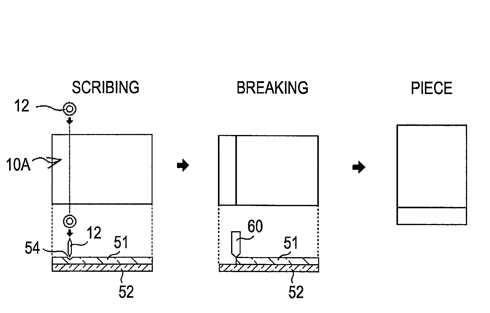
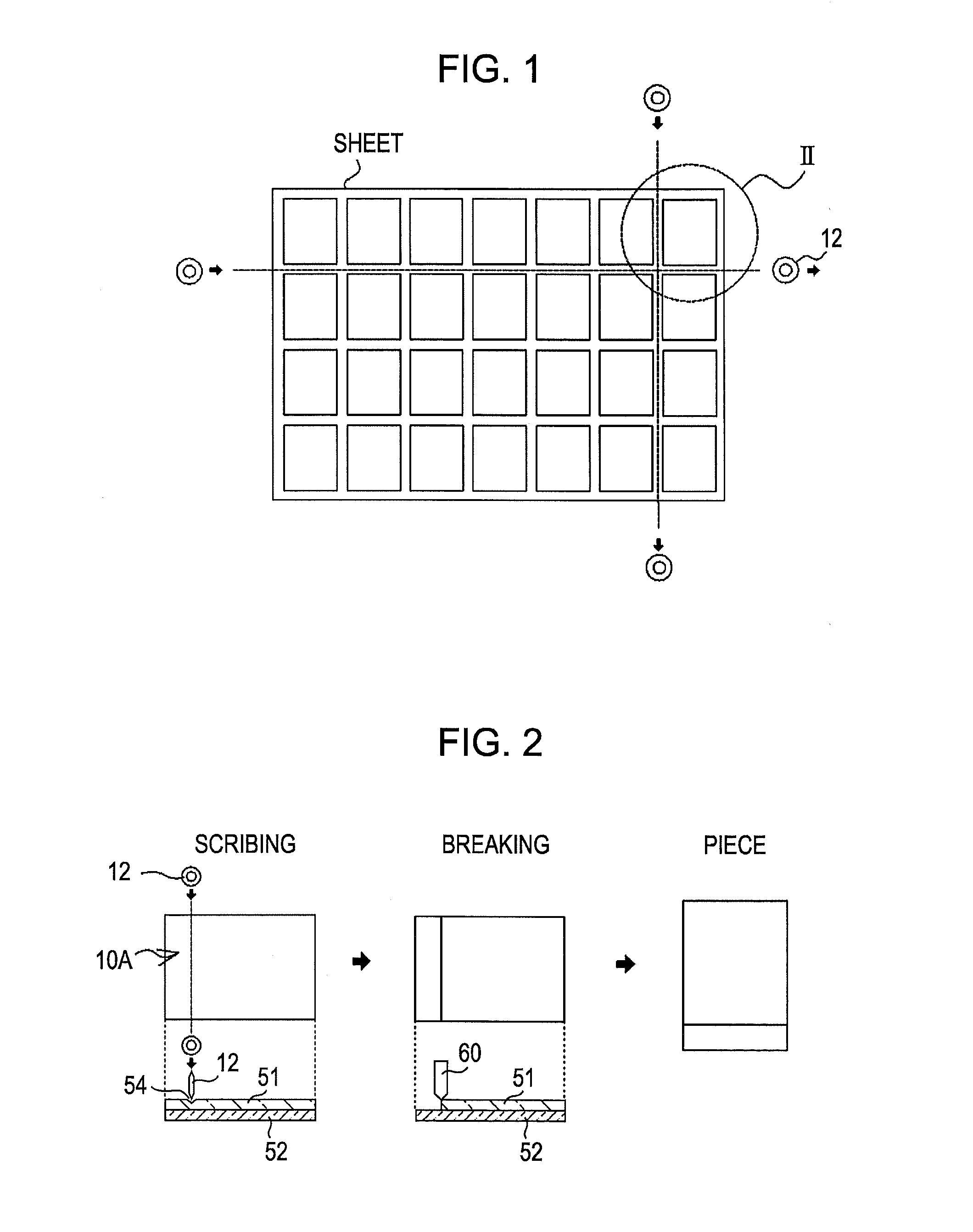
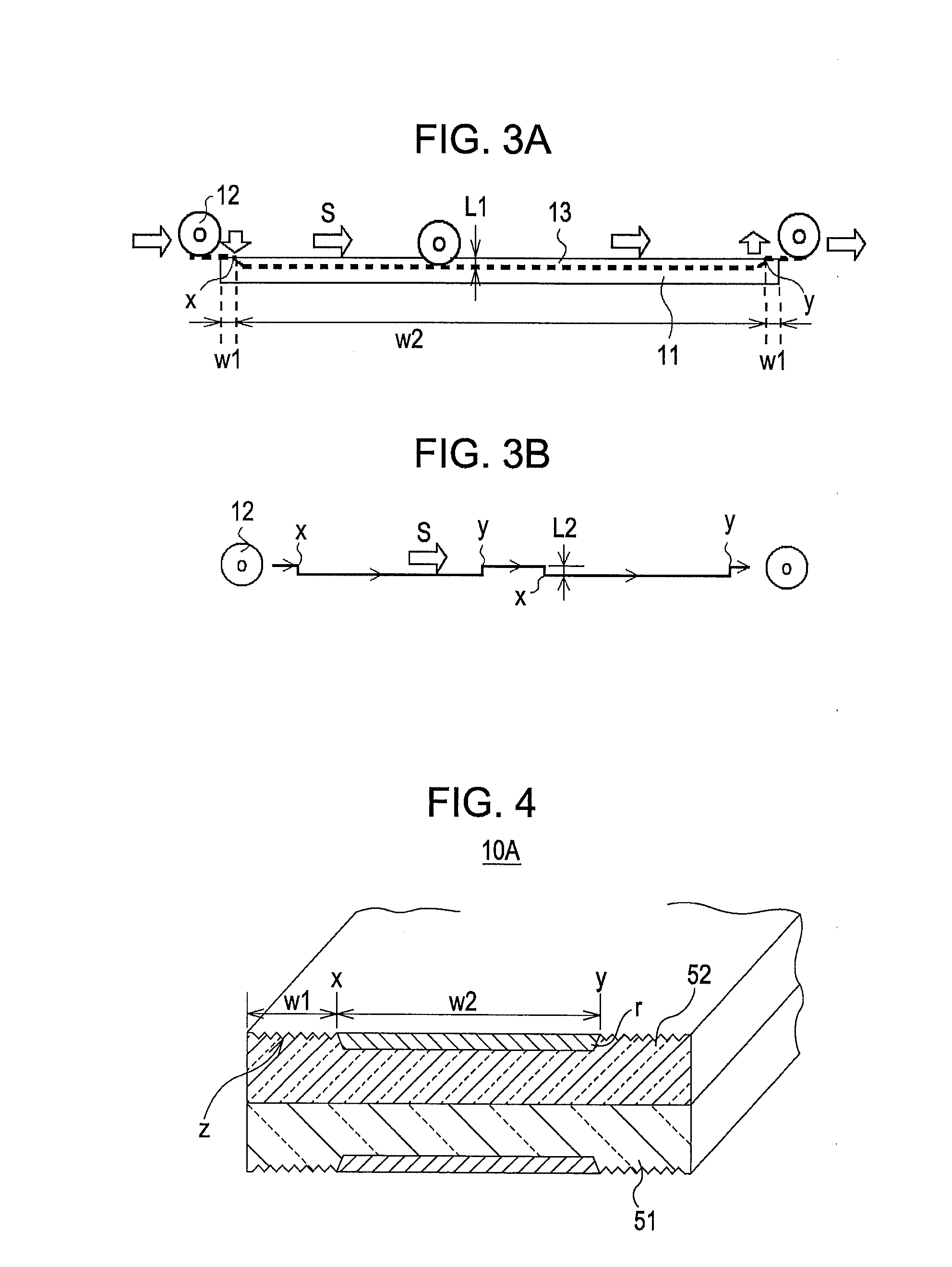
A display device includes a pair of glass substrates. On the side of each of the pair of glass substrates, a press mark is formed between a first end of each of the pair of glass substrates and a position at least 0.3 mm but no more than 3 mm away from the first end, another press mark is formed between a second end of each of the pair of glass substrates and a position at least 0.3 mm but no more than 3 mm away from the second end, a scribing groove having a predetermined scribing amount is formed between the press marks, and there are rib marks in the scribing groove.
Description
BACKGROUND[0001]1. Technical Field[0002]The present invention relates to a display device having a pair of glass substrates and a method for cutting it. Specifically, the invention relates to a display device having a pair of glass substrates and a method for cutting it in which, when a glass substrate of a display device is cut by an internal scribing method, vertical movement of a scribing wheel is reduced to improve the cutting efficiency, and that is less prone to cracking, chipping, and waste residue.[0003]2. Related Art[0004]Thin display devices such as LCDs have a bonded glass substrate pair. A process for manufacturing such display devices having a bonded glass substrate pair includes a process for cutting a large glass substrate pair into separate pieces and a process for cutting off peripheral portions. In such cutting processes, there is generally used a process including forming a scribing groove (also called “scribing”) using, for example, a sintered diamond cutter (scr...
Claims
Login to View More Application Information
Patent Timeline
 IPC IPC(8): H01J9/00B26F3/00C03B33/00G02F1/133
CPCC03B33/023C03B33/027C03B33/07G02F1/133351Y10T428/24777Y10T428/2457Y10T428/24612Y10T428/15H01J9/241Y02P40/57Y10T225/12
InventorKAWAMOTO, SATORU
OwnerJAPAN DISPLAY WEST