

Dynamic Ball Valve Sealing Device For Three-Way Valves
Patent Information
- Authority / Receiving Office
- US · United States
- Current Assignee / Owner
- TAC LLC
- Publication Date
- 2008-12-25
Smart Images
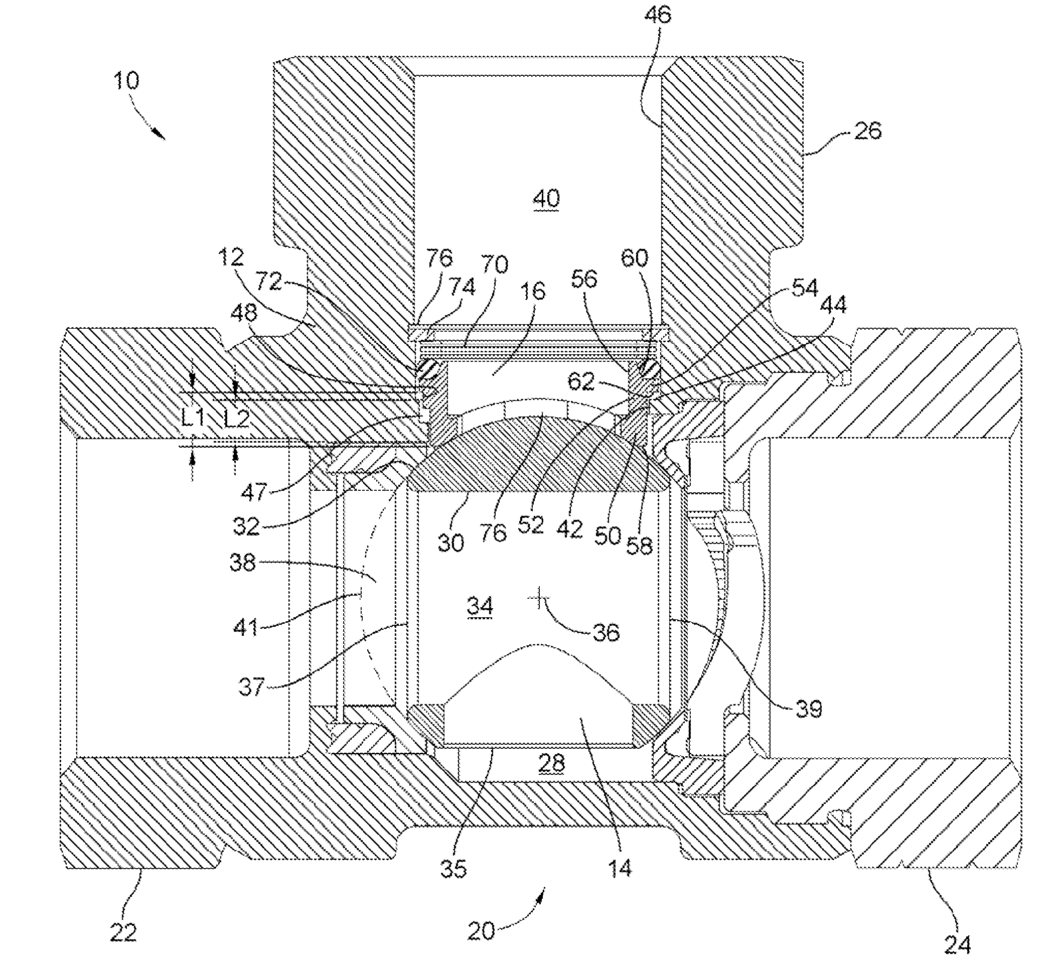
Figure 1 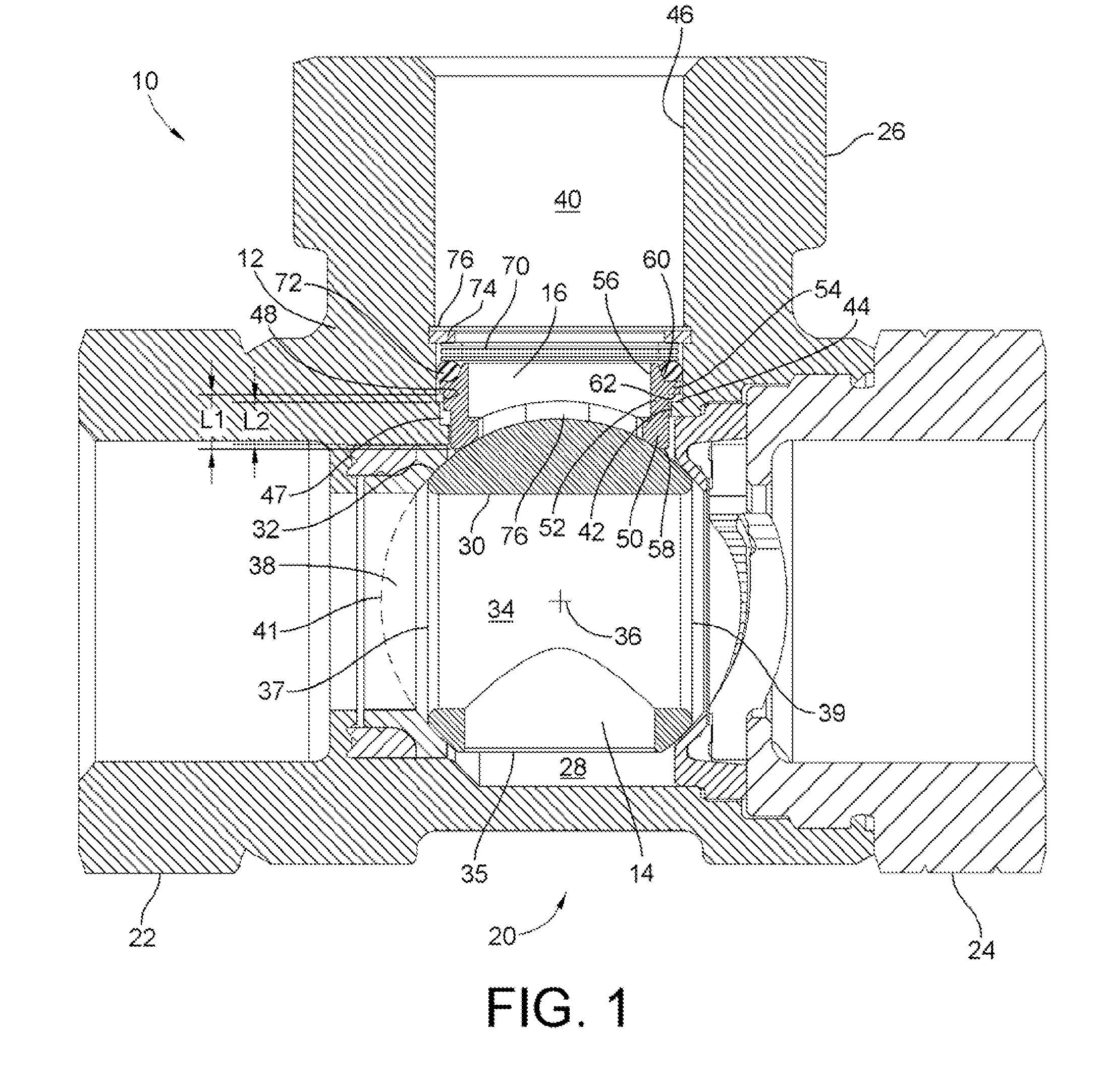
Figure 2 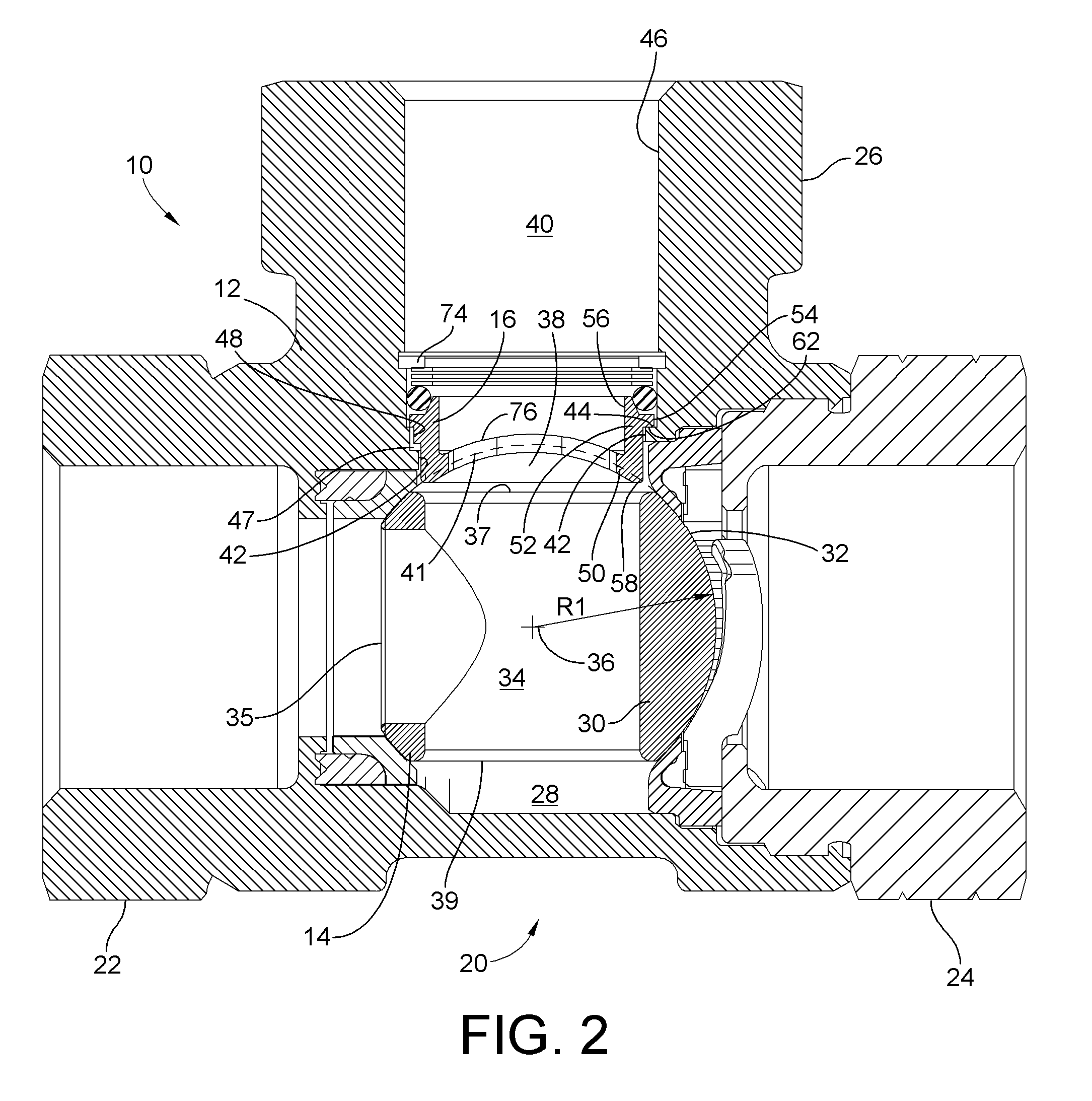
Figure 3
Abstract
Description
FIELD OF THE INVENTION
[0001] This invention generally relates to ball valves and more particularly relates to an apparatus and method for dynamically sealing the valve member of a ball valve.BACKGROUND OF THE INVENTION
[0002] Ball valves typically include a valve body that includes a plurality of ports typically ranging between two ports and four ports. A valve member within the valve body, depending on its orientation within the valve body, selectively directs fluid between selected ones of the various ports or may entirely stop fluid flow through the valve body. As such, ball valves include seals interposed between the various ports and the valve member to prevent fluid from bypassing the valve member, i.e. leaking around the valve member and circumventing the desired fluid flow configuration.
[0003] Unfortunately, due to machining tolerances of the valve member and valve body, it has been difficult to ideally place and size fixed position seals for perfect, leak-free, seal-off. Furthe...