Swithgear cell and converter circuit for switching a large number of voltage levels

a converter circuit and voltage level technology, applied in the field of converter circuits, can solve the problems of increasing susceptibility to interference, requiring a large amount of space in the converter circuit, and low availability, and achieve the effect of small space requirement and simple and robust converter

Inactive Publication Date: 2008-12-25
ABB RES LTD
View PDF3 Cites 31 Cited by
  • Summary
  • Abstract
  • Description
  • Claims
  • Application Information

AI Technical Summary

Problems solved by technology

This is accompanied by a very high circuitry outlay and, with regard to the power semiconductor switches, also a very high driving outlay, which typically results in an increased susceptibility to interference and hence low availability.
Moreover, such a converter circuit requires a large amount of space.

Method used


Image

  • Swithgear cell and converter circuit for switching a large number of voltage levels
  • Swithgear cell and converter circuit for switching a large number of voltage levels
  • Swithgear cell and converter circuit for switching a large number of voltage levels

Examples


Embodiment Construction

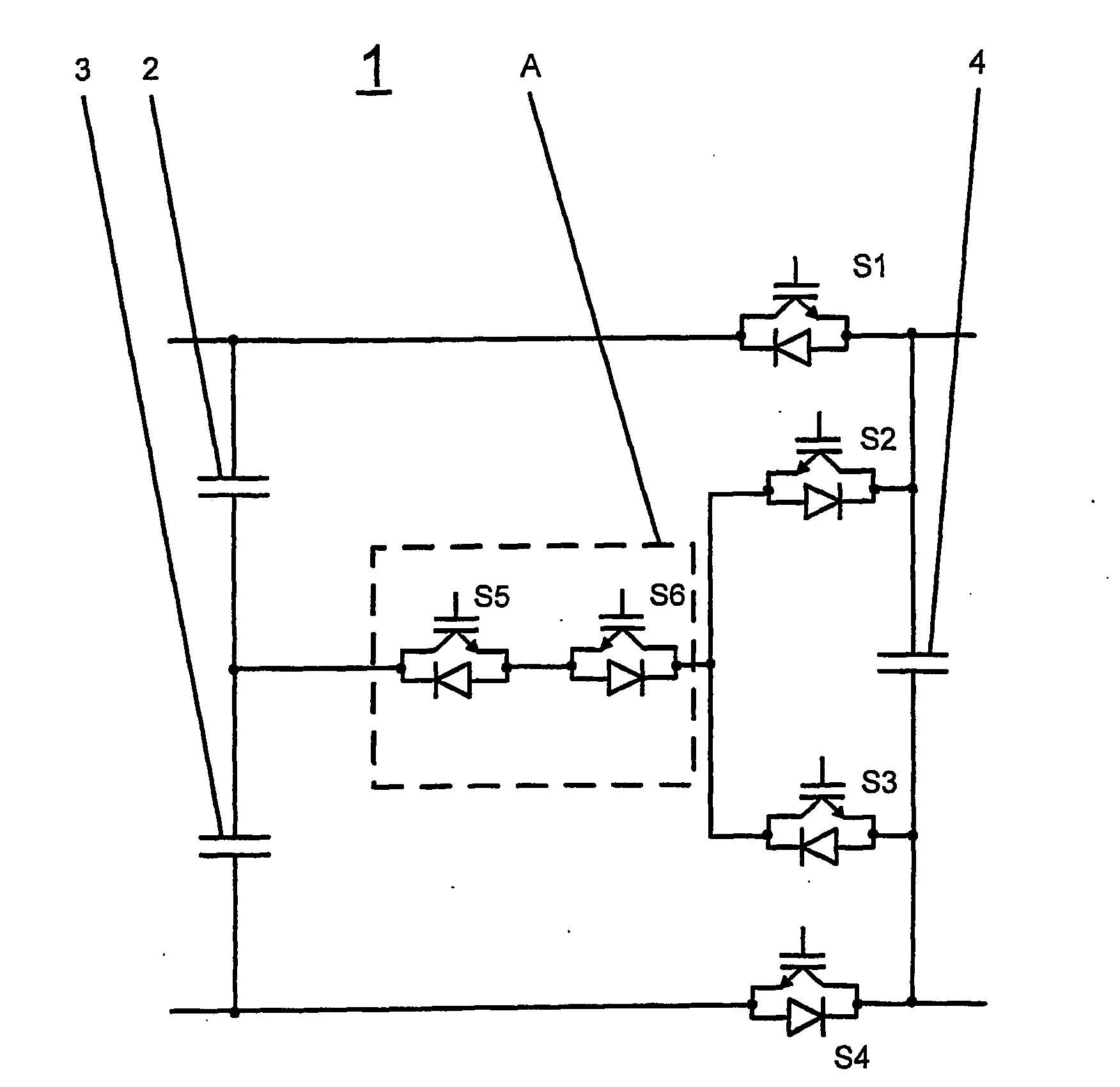
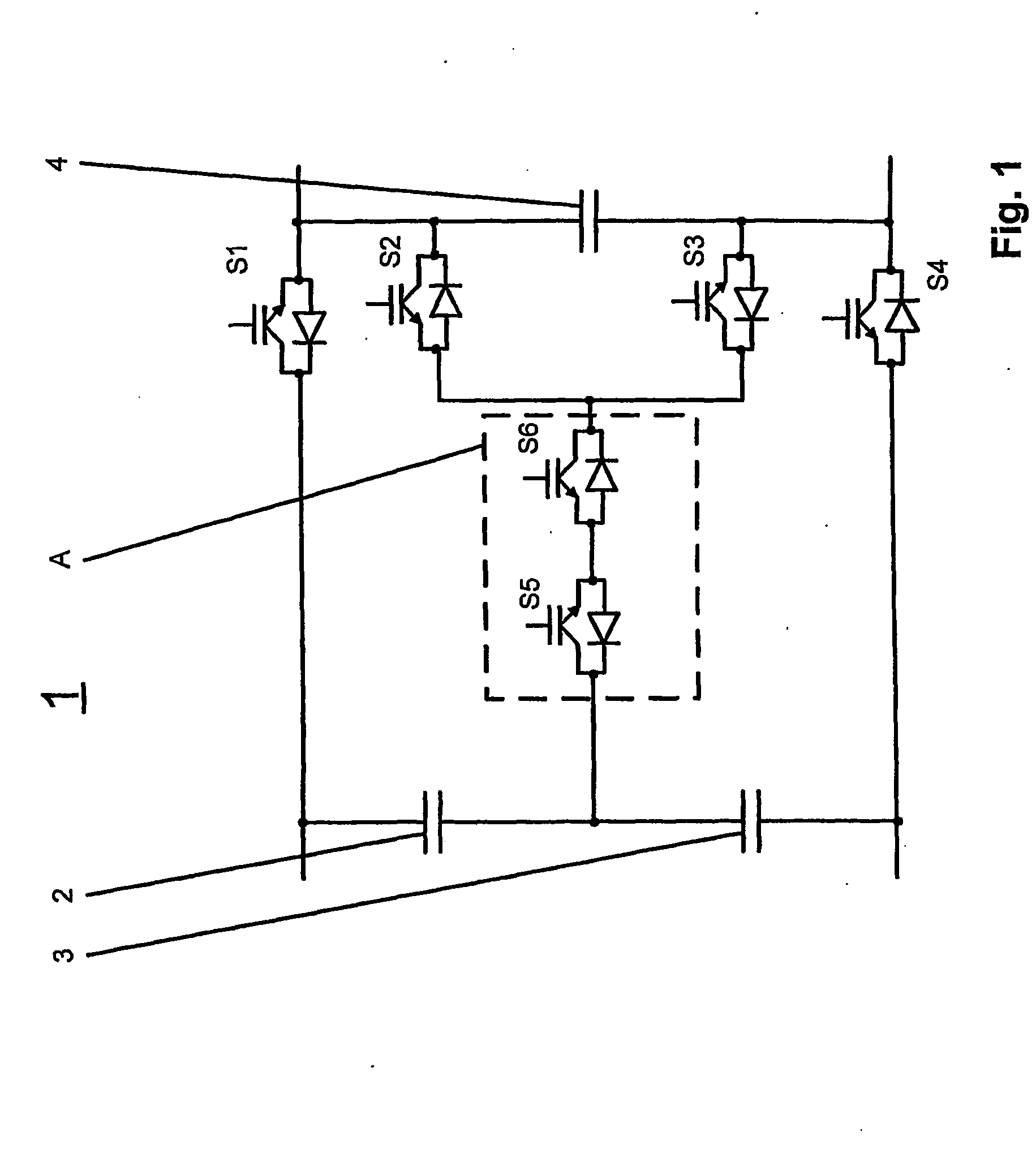
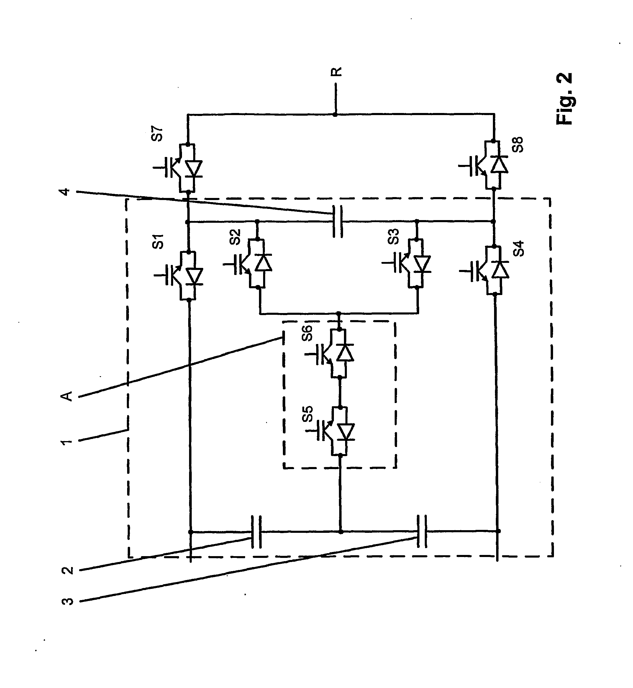
[0023]The switchgear cell, according to the disclosure for switching a large number of voltage levels has a first energy store and a second energy store connected in series with the first energy store. Furthermore, the switchgear cell has a first, second, third and fourth power semiconductor switch, wherein the first, second, third and fourth power semiconductor switch are in each case a drivable bidirectional power semiconductor switch with a controlled unidirectional current-carrying direction and the first, second, third and fourth power semiconductor switch are connected in series and the first power semiconductor switch is connected to the first energy store and the fourth power semiconductor switch is connected to the second energy store. Furthermore, a third energy store is connected to the junction point between the first power semiconductor switch and the second power semiconductor switch and to the junction point between the third power semiconductor switch and the fourth ...


PUM


Abstract

A switchgear cell is disclosed having a first energy store and a second energy store connected in series therewith, having a first, second, third and fourth power semiconductor switch, which are connected in series, wherein the first, second, third and fourth power semiconductor switch are in each case one drivable bidirectional power semiconductor switch with a controlled unidirectional current-conducting direction. The first power semiconductor switch is connected to the first energy store, and the fourth power semiconductor switch is connected to the second energy store. A third energy store is connected to the junction between the first and the second power semiconductor switch and the junction between the third and the fourth power semiconductor switch.

Description

RELATED APPLICATIONS[0001]This application claims priority under 35 U.S.C. §119 to European Application 06405047.9 filed in Europe on Feb. 1, 2006, and as a continuation application under 35 U.S.C. §120 to PCT / CH2006 / 000699 filed as an International Application on Dec. 14, 2006 designating the U.S., the entire contents of which are hereby incorporated by reference in their entireties.TECHNICAL FIELD[0002]The disclosure relates to the field of converter circuits. It is based on a switchgear cell and on a converter circuit for switching a large number of voltage levels.BACKGROUND INFORMATION[0003]At the present time power semiconductor switches are being used increasingly in converter technology and in particular in converter circuits for switching a large number of voltage levels. Such a converter circuit for switching a large number of voltage levels is specified in “A Generalized Multilevel Inverter Topology with Self Voltage Balancing”, IEEE Transactions on Industry Applications, ...

Claims


Application Information

Patent Timeline
Patent Type & Authority Applications(United States)
IPC IPC(8): G05F1/44
CPCH02M7/487H02M2007/4835H02M1/0095H02M7/4837H02M7/48H02M7/797
Inventor PONNALURI, SRINIVASHADERLI, CHRISTOPH
Owner ABB RES LTD
Why Eureka
Try Eureka