
Computer Mouse

Inactive Publication Date: 2008-12-25
INDIGOLAB
View PDF7 Cites 1 Cited by
  • Summary
  • Abstract
  • Description
  • Claims
  • Application Information

AI Technical Summary

Benefits of technology

[0010]The present invention provides a computer mouse including a grip portion and a sensor, both of which have improved structures so that it is possible to reduce joint fatigue in the hand or wrist of a user and rapidly move a cursor on a computer screen during various computer tasks.

Problems solved by technology

Therefore, there are problems in that the movement speed of the sensor is low, and the cursor cannot be moved fast enough to play a game or work.
In addition, in order to move the cursor to the left or right on the computer screen, the user has to move the wrist to the left or right, and thus the wrist joint and muscles can be damaged.
Moreover, since the user holds the mouse with the thumb, the middle finger or the ring finger, and the little finger, the positions of the fingers are not natural.
Therefore, when the user uses the mouse for a long period of time, finger joints can also be damaged.

Method used


Image

  • Computer Mouse
  • Computer Mouse
  • Computer Mouse

Examples


Embodiment Construction

[0040]Hereinafter, exemplary embodiments of the present invention will be described in detail with reference to the attached drawings.

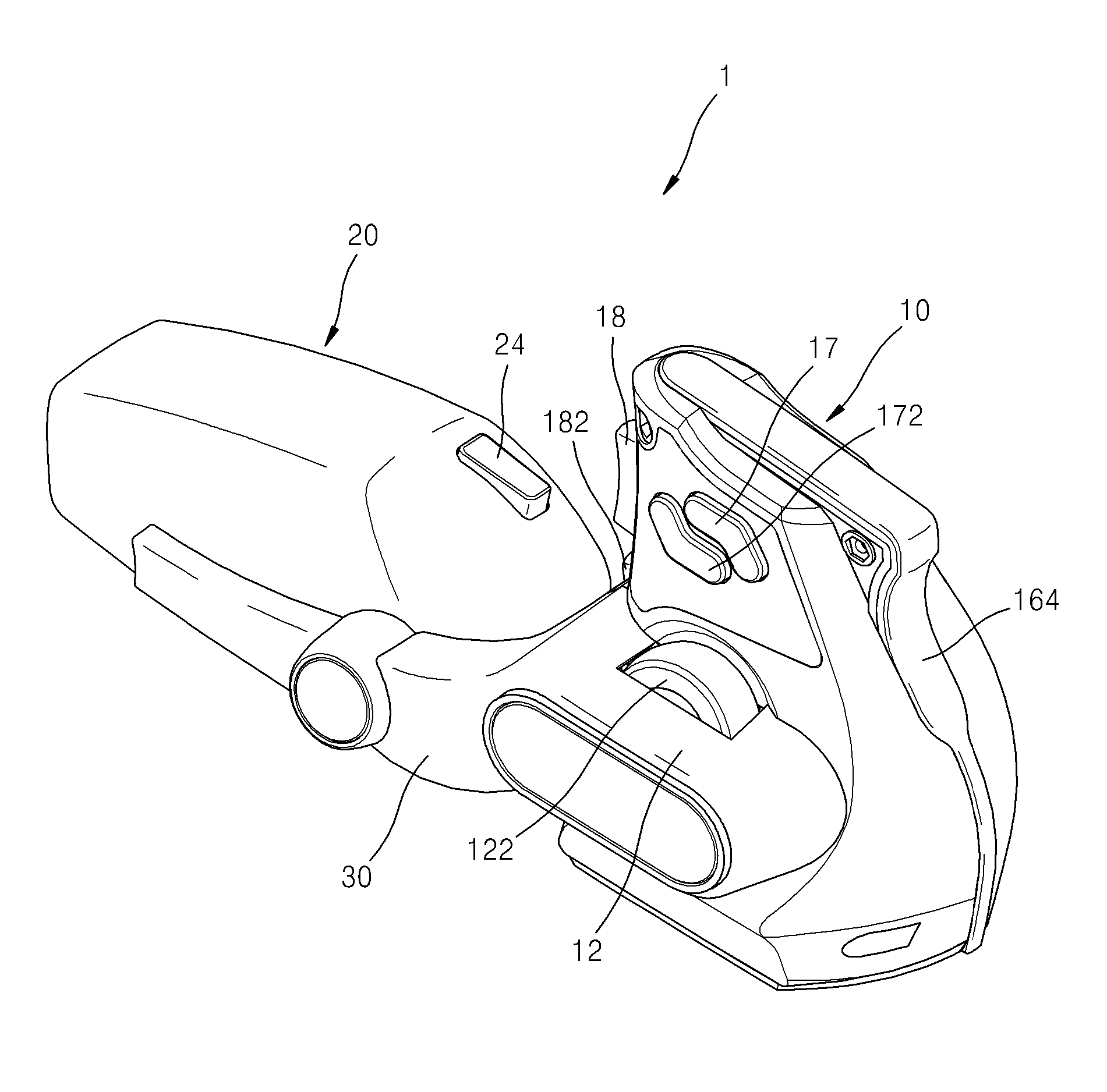
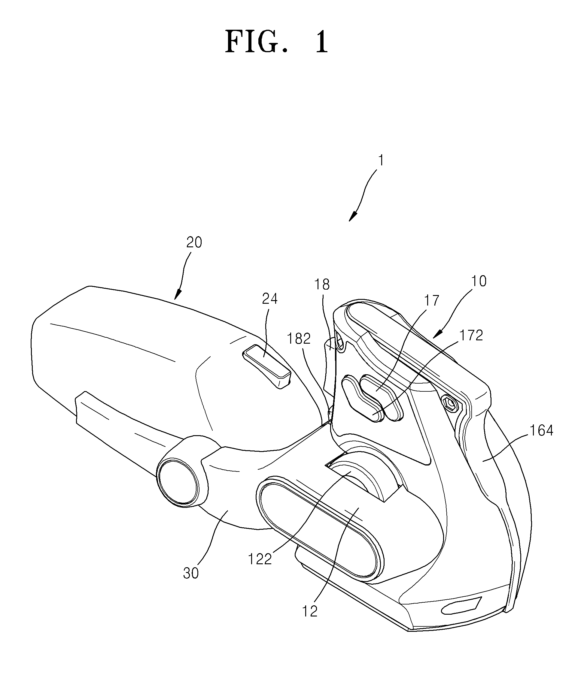
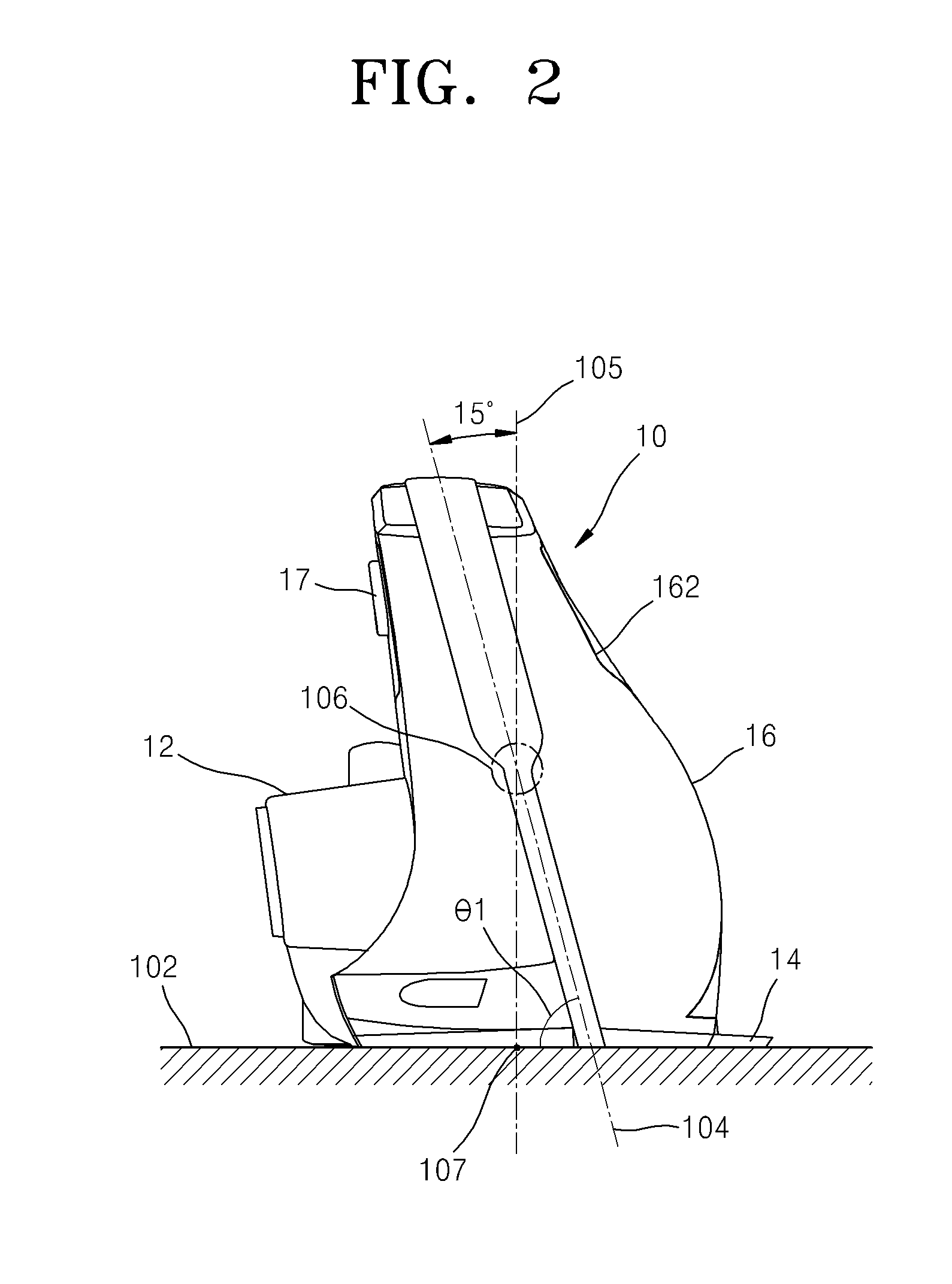
[0041]FIG. 1 is a left rear side view of a computer mouse 1 according to an embodiment of the present invention. FIGS. 2 and 3 are rear side and the right side views of the computer mouse 1, respectively. FIG. 4 is a bottom plan view of the computer mouse 1. FIGS. 5 and 6 are right rear side and left front side perspective views of the computer mouse 1 of FIG. 1, respectively.

[0042]As shown in FIGS. 1, 2, 3, 4, and 5, the computer mouse 1, which is used as an input device of a computer, includes a grip portion 10, a sensor portion 20, a connection portion 30, and an interface cable 40.

[0043]The grip portion 10 is standing on a surface 102 (see FIG. 2) on which the computer mouse 1 moves horizontally. A user holds the grip portion 10 to use the mouse 1.

[0044]A virtual central axis 104 passing through the grip portion 10 is tilted to the left or right. ...


PUM


Abstract

Provided is a computer mouse including a grip portion having a flat bottom surface and a longitudinal central grip axis; a grip central point located at the center of the longitudinal central grip axis; the grip portion standing on a surface on which the computer mouse moves; a vertical axis perpendicular to the surface and including the central point; a sensor portion which includes a sensor having a sensor central point located at the center of the sensor; the sensor being located distant in a forward direction from the grip portion; a vertical plane containing the vertical axis and the sensor central point; wherein the longitudinal central axis is angled from the vertical axis and tilted to the left or right with reference to the forward direction; a bottom grip point defined by the intersection between the vertical axis and the bottom surface; and wherein the bottom grip point is located substantially at the center of the bottom surface.

Description

CROSS-REFERENCE TO RELATED PATENT APPLICATION[0001]This application claims the benefits of Korean Patent Application No. 10-2007-0060608, filed on Jun. 20, 2007 in the Korean Intellectual Property Office, the disclosure of which is incorporated herein in its entirety by reference.BACKGROUND OF THE INVENTION[0002]1. Field of the Invention[0003]The present invention relates to a computer mouse, and more particularly, to a computer mouse including a grip portion and a sensor portion in order to minimize wrist fatigue and rapidly move a cursor on a screen.[0004]2. Description of the Related Art[0005]A mouse is a computer input device that controls the movement of a cursor on a display screen during various computer tasks. A conventional mouse includes a sensor having a rubber or metal ball or an optical sensor in the center portion of a lower surface and at least one button and sometimes as many as three at an upper frontal portion, the buttons having different functions depending on a ...

Claims


Application Information

Patent Timeline
IPC IPC(8): G09G5/00
CPCG06F3/03543G06F3/0354
Inventor KIM, CHEOL HO
Owner INDIGOLAB
Learn More