
System and method for rapidly shaking an implement of a machine

Inactive Publication Date: 2009-03-05
CATERPILLAR INC
View PDF15 Cites 13 Cited by
  • Summary
  • Abstract
  • Description
  • Claims
  • Application Information

AI Technical Summary

Benefits of technology

[0007]The disclosure describes, in another aspect, a method of controlling the displacement of a source in a machine for providing a fluid flow to an actuator that provides for rapid movement of an implement. The method includes establishing an indicator characterized by a pattern of input commands that indicate

Problems solved by technology

This design can waste fuel and subjects the machine, including the pump and the engine, to unnecessary wear.

Method used


Image

  • System and method for rapidly shaking an implement of a machine
  • System and method for rapidly shaking an implement of a machine
  • System and method for rapidly shaking an implement of a machine

Examples


Embodiment Construction

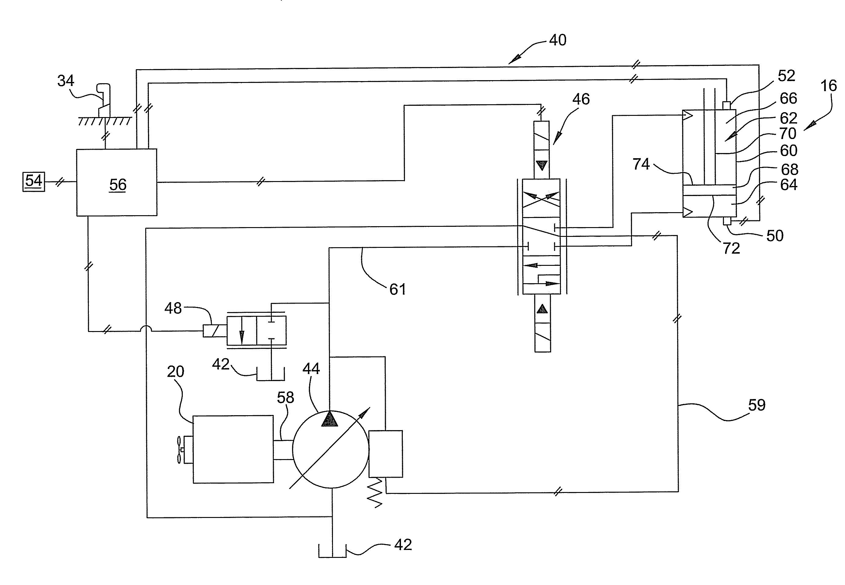
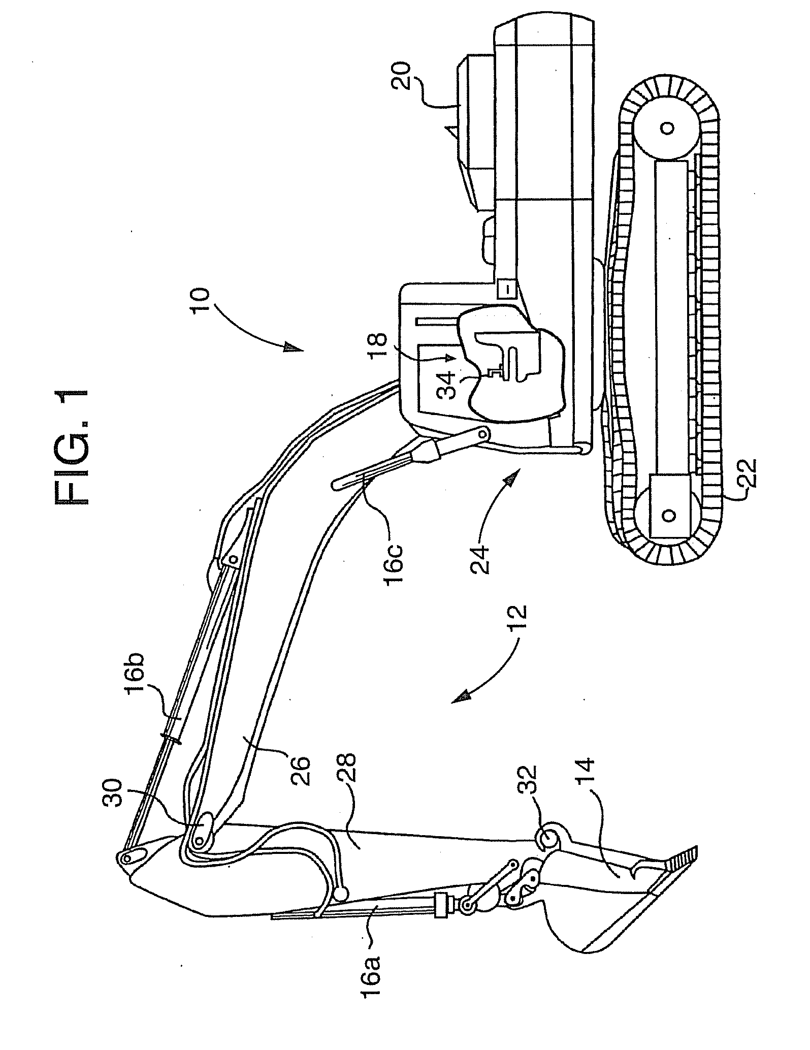
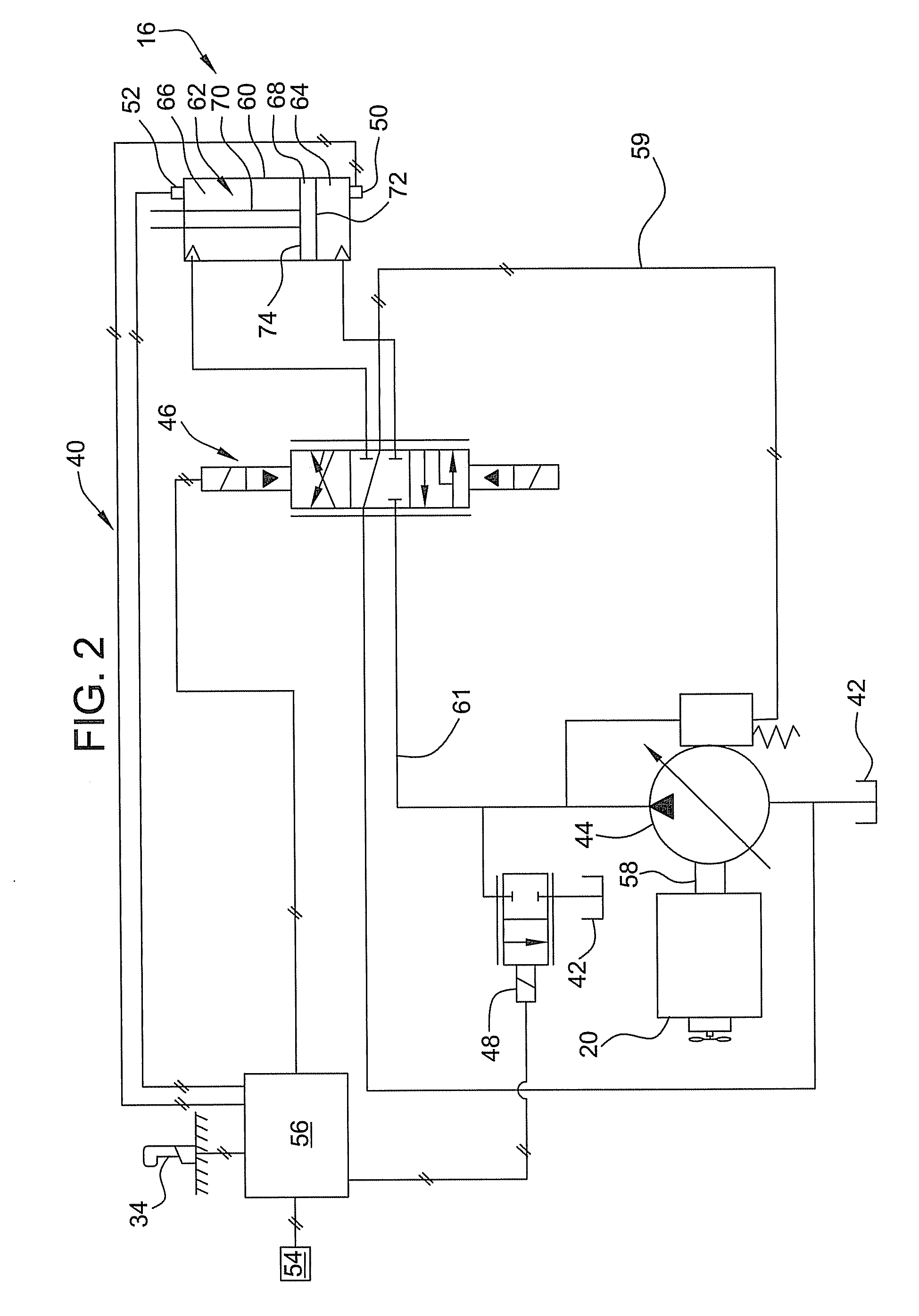
[0012]This disclosure relates to a system and method for controlling a flow of hydraulic fluid in a hydraulic system of a machine. In particular, a controller applies one or more modes to control a rate of flow of hydraulic fluid to an actuator in the machine when an operator requests rapid shaking of an implement. This rapid shaking can, for example, dislodge mud, dirt, clay or debris from the implement.

[0013]FIG. 1 illustrates an exemplary machine 10. The machine 10 may be a fixed or mobile machine that performs an operation associated with an industry such as, for example mining, construction, farming, or transportation. For example, the machine 10 may be an earth moving machine such as an excavator, a dozer, a loader, a backhoe, a motor grader, or any other earth moving machine. The machine 10 may include a linkage system 12, an implement 14 attachable to linkage system 12, one or more hydraulic actuators 16a-c interconnecting the linkage system 12, an operator interface 18, a p...


PUM


Abstract

A fluid system for use with a machine that employs an actuator, that provides for rapid shaking of an implement. The fluid system includes a source for providing fluid flow to the actuator and an operator input device for enabling an operator to control the movement of the implement by inputting a plurality of commands that specify movement of the implement. A controller is provided for monitoring the commands received from the operator input device and entering a mode for controlling the displacement of the source when the controller detects a pattern of commands that indicates an operator-request for rapid movement of the implement.

Description

TECHNICAL FIELD[0001]This patent disclosure relates generally to a hydraulic system and, more particularly, to a hydraulic system for use in a machine that employs an implement.BACKGROUND[0002]Many machines use hydraulic actuators to accomplish a variety of tasks, such as moving an implement. Examples of such machines include, without limitation, dozers, loaders, excavators, motor graders, and other types of heavy machinery. The hydraulic actuators in such machines are linked via fluid flow lines to a pump associated with the machine to provide pressurized fluid to the hydraulic actuators. Chambers within the various actuators receive the pressurized fluid in controlled flow rates in response to operator demands or other signals. The pump can be a load-sense hydraulic pump that, in response to the magnitude of the load acting on the implement, automatically varies the flow rate of the pressurized fluid. For example, when the implement encounters a heavy load, the load-sense hydrauli...

Claims


Application Information

Patent Timeline
IPC IPC(8): F15B21/00
CPCE02F9/221F15B21/082F15B2211/20523F15B2211/7733F15B2211/327F15B2211/6346F15B2211/7053F15B2211/20546
Inventor BRINKMAN, JASON L.KUEHN, JEFFREY L.
Owner CATERPILLAR INC
Learn More